RF3000 Просмотр технического описания (PDF) - RF Micro Devices
Номер в каталоге
Компоненты Описание
Список матч
RF3000 Datasheet PDF : 28 Pages
| |||
RF3000
Another optional mode has been added to the AGC algorithm. This mode adds a delay into the algorithm after the LNA
gain select is changed to allow enough time for the radio to settle properly. The delay eliminates the possibility of a 'dead
zone' where there is a small range of input power levels with a probability that the AGC will settle to an incorrect gain set-
ting. To enable this mode, Register 0x1D is written to 0x80. In addition, the 6 lsb's of reg20 must be set to 4 higher the 6
lsb's of reg21 because the outcome of the AGC decision step will change. If this mode is not to be used, Register 0x1D
should be written to 0x00.
AGC Calibration
The RF3000 is preprogrammed for a “typical” radio. The default settings of the RF3000 may be used without modifica-
tion, but the conditions of the AGC algorithm may be modified by writing to register 21 and register 20 of the control port.
Register 21 controls an offset to the RXVGC DAC for LNAGS=1 (high gain mode), and register 20 controls an offset to
the RXVGC DAC for LNAGS=0 (low gain mode). Caution should be taken when setting these registers; incorrect set-
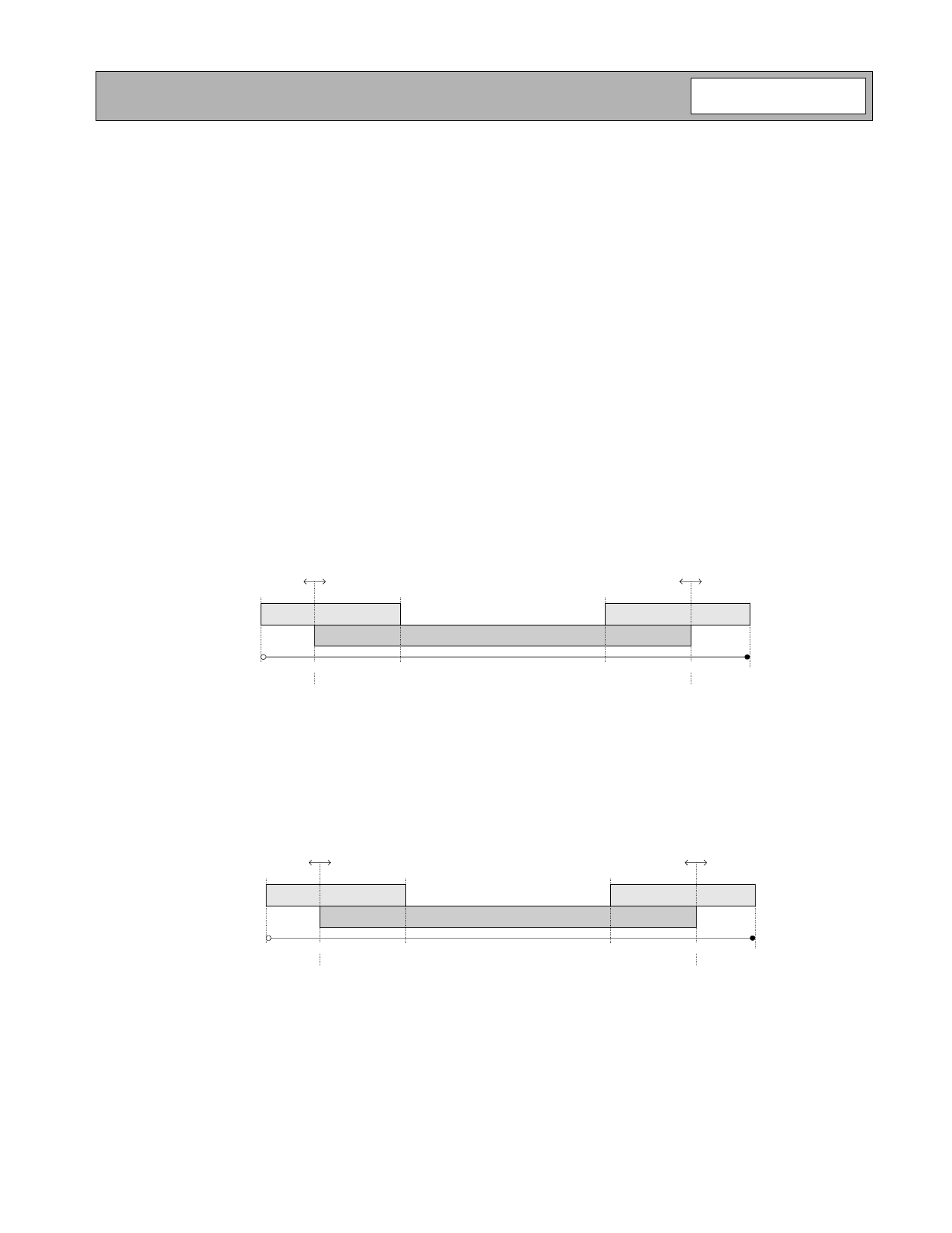
tings can create a “dead zone” between the high/low gain trees. The following figure shows the “typical” settings for the
RXVGC output of the RF3000 during LNAGS=1. Also shown are the expected production variances of an IEEE802.11
radio, and the calibration ranges of the RF3000. Writing to register 21 of the RF3000 will move the range of AGC opera-
tion on the RXVGC pin. For example, if the six LSB's in register 21 are written to 000100b (4 decimal), the starting point
for the AGC algorithm (max gain) will be with a DAC code of 8+4=12 codes, and the LNAGS decision will be made at a
code of 47+4=51 codes. This has the overall effect of decreasing the gain provided by the RF2948 by four D/A codes or
approximately 5dB for both initial AGC setting for detection of saturation and for determining LNAGS. Likewise if the six
LSB's of register 21 are written to 1111000 (-4 decimal), the initial condition that the RF3000 uses to look for saturation
is 8-4=4 codes, and the LNAGS decision is determined at 47-4=43 codes.
Process
Variation
Process
Variation
Cal Range
D/A Code
0
Typical
RF2948
Gain
8
67.8dB
Typical RF3000 AGC Range
24
39
Cal Range
47
63
21.7dB
Figure 11. High Gain Mode (LNAGS=1) Plot of RXVGC Showing Normal Operation and Calibration Ranges
Similar to the high gain calibration, register 20 controls an offset into the LNAGS=0 (low gain mode) values that are
applied to the D/A converter. The figure below shows the normal operation range of the RF3000 and the calibration
range that is provided.
Process
Variation
Process
Variation
Cal Range
D/A Code
0
Typical
RF2948
Gain
8
67.8dB
Typical RF3000 AGC Range
17
39
Cal Range
54
63
13.4dB
Figure 12. Low Gain Mode (LNAGS=0) Plot of RXVGC Showing Normal Operation and Calibration Ranges
Rev A4 031216
11-335
Share Link: 