HFB50HC20C(2001) Просмотр технического описания (PDF) - International Rectifier
Номер в каталоге
Компоненты Описание
Список матч
HFB50HC20C Datasheet PDF : 5 Pages
| |||
HFB50HC20C
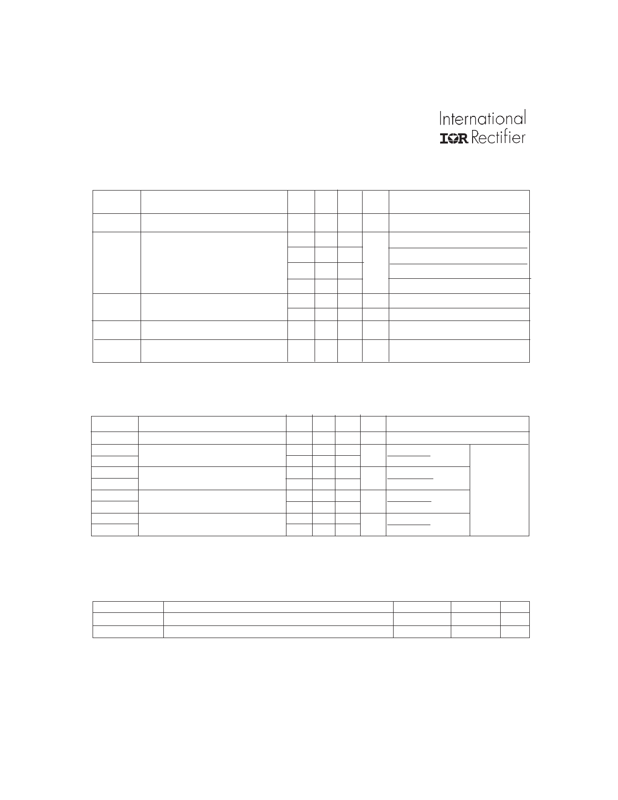
Electrical Characteristics ( Per Leg )@ TJ = 25°C (unless otherwise specified)
Parameter
Min. Typ. Max. Units
Test Conditions
VBR
Cathode Anode Breakdown Voltage
200 — —
V IR = 100µA
VF
Forward Voltage
— — 1.36
IF = 25A, TJ = -55°C
See Fig. 1
—
— 1.20
V
IF = 25A, TJ = 25°C
See Fig. 2
— — 1.49
IF = 50A, TJ = 25°C
— — 0.99
IF = 25A, TJ = 125°C
IR
Reverse Leakage Current
See Fig. 2
— — 1.0 µA VR = VR Rated
— — 100 µA VR = VR Rated, TJ = 125°C
CT
Junction Capacitance, See Fig. 3
— — 200 pF VR = 200V
LS
Series Inductance
— 8.7 —
nH Measured from anode lead to cathode
lead , 6mm ( 0.025 in) from package
Dynamic Recovery Characteristics ( Per Leg ) @ TJ = 25°C (unless otherwise specified)
trr
trr1
trr2
IRRM1
IRRM2
Qrr1
Qrr2
di(rec)M/dt1
di(rec)M/dt2
Parameter
Reverse Recovery Time
Reverse Recovery Time
Peak Recovery Current
Reverse Recovery Charge
Peak Rate of Fall of Recovery Current
During tb
Min. Typ. Max. Units
Test Conditions
— — 35 ns IF = 0.5A,VR = 30V, dif/dt = 300A/µs
— 46 — ns TJ = 25°C See Fig.
— 84 —
TJ = 125°C
5
IF = 50A
— 5.7 —
— 12.5 —
A TJ = 25°C See Fig.
A TJ = 125°C
6
VR = 160V
— 150 — nC TJ = 25°C See Fig.
— 595 — nC TJ = 125°C
7 dif/dt = 200A/µs
— 530 — A/µs TJ = 25°C See Fig.
— 1130 — A/µs TJ = 125°C
8
Thermal - Mechanical Characteristics
RthJC
Wt
Parameter
Junction-to-Case, Single Leg Conducting
Weight
Typ.
—
10.9
Max.
0.96
—
Units
°C/W
g
2
www.irf.com
Share Link: 