GL711FW Просмотр технического описания (PDF) - Unspecified
Номер в каталоге
Компоненты Описание
Список матч
GL711FW Datasheet PDF : 17 Pages
| |||
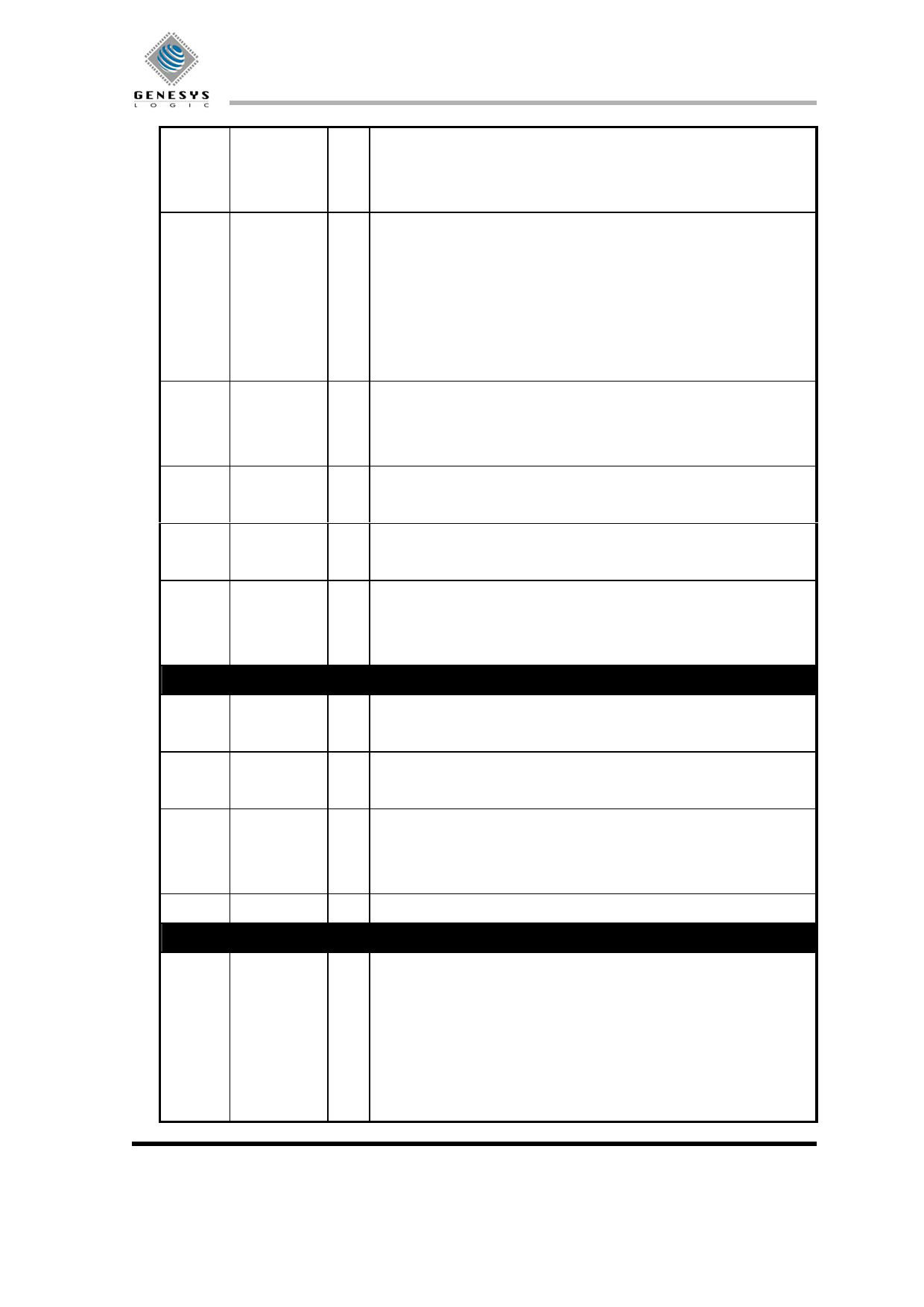
GL711FW
45
HDIOR#(HD O Device I/O read (for PIO and Multi-word DMA mode)
MARDY#/,
Ultra DMA host ready (for UDMA read)
HDSTROBE)
Ultra DMA host data strobe (for UDMA write)
48,51,53, HDD15-0 I/O IDE device data. The 8- or 16-bit data bus to/from the ATA device.
56,59,61,
Only the lower 8 bits are used for 8-bit register transfers.
64,66,67,
65,63,60,
58,55,52,
49
44
HDIORDY(D I I/O channel ready (for PIO and Multi-word DMA mode)
DMARDY#/,
Ultra DMA device ready (for UDMA write)
DSTROBE)
Ultra DMA device data strobe (for UDMA read)
42
HDINT
I IDE device interrupt: This input signal is used to interrupt the host
system when interrupt pending is set.
43
HDDACK# O IDE DMA acknowledge: This signal is used by the ATA host to
response DMARQ for DMA transfers.
47
HDDRQ
I IDE DMA request: This signal is asserted by the ATA device when it
is ready to perform a DMA data transfer to or from the ATA host
when a DMA operation has been enabled.
Signals for PHY-interface
15,16 PHY_CTL1 I/O Control 1 and Control 0 of the phy-link control bus. CTL1 and CTL0
PHY_CTL0
indicate the four operations that can occur in this interface.
18
LREQ
O Link request. LREQ is a output that makes bus requests and accesses
the phy layer.
6-9,11-14 PHY_D7-0 I/O Phy data7 through data0 of the phy-link data bus. Data is expected on
D0-D1 for 100Mb/s packets, D0-D3 for 200Mb/s, and D0-D7 for
400Mb/s.
17
PHY_SCLK I System clock. PHY_SCLK is a 49.152-MHz clock from the phy.
Signals for flash memory
81,33,87, ADDR[15:0] O Flash PROM/EPROM address bus.
83,91,93,
ADDR15 is the most significant bit.
89,88,82,
79,78,77,
75,74,73,
72
Revision: 1.3
-13-
09/12/2001
Share Link: 