TDA7580 Просмотр технического описания (PDF) - STMicroelectronics
Номер в каталоге
Компоненты Описание
Список матч
TDA7580 Datasheet PDF : 39 Pages
| |||
TDA7580
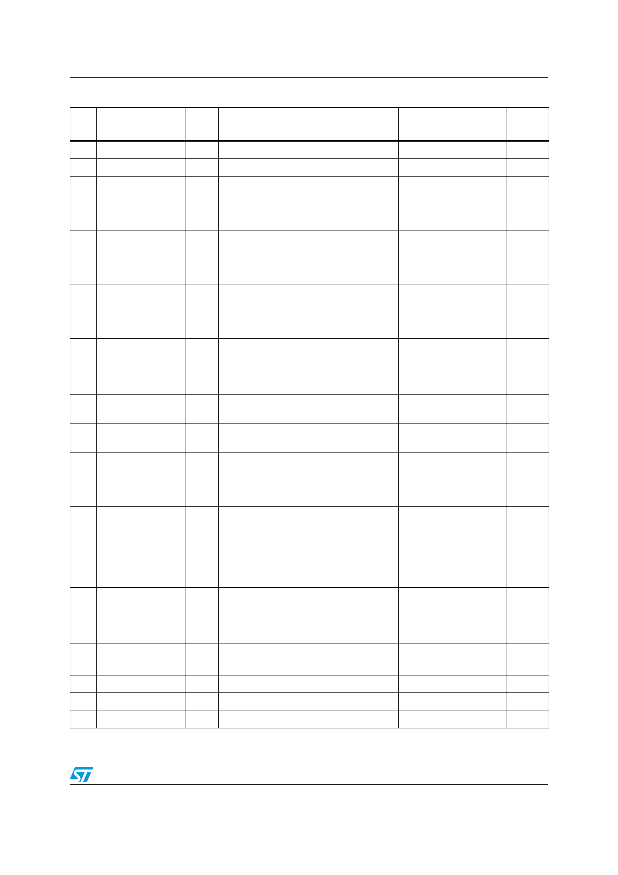
Block diagram and electrical specifications
Table 5. Pin description (continued)
N°
Name
Type
Description
Notes
21 GND
22 VDD
23 IQSYNC
24 IQCH1
25 IQCH2
26 IQCH3
27 VDDH
28 GNDH
29 RDS_INT
30 RDS_CS
31 INT
32 ADDR_SD
33 RESETN
34 VDD
35 GND
36 TESTN
G Digital core power ground
P Digital core power supply
1.8V
High speed synchronous serial interface DSP1 GPIO0
B
(HS3I) clock if HS3I master mode, else
DSP1 GPIO or DSP1 debug port clock
5V tolerant. With
internal pull-up, on at
(DBOUT1)
reset
High speed synchronous serial interface DSP1 GPIO1
B
(HS3I) channel 1 data if HS3I master
5V tolerant. With
mode, else DSP1 GPIO or DSP1 debug internal pull-up, on at
port request (DBRQ1)
reset [PP]
High speed synchronous serial interface DSP1 GPIO2
B
(HS3I) channel 2 data if HS3I master
5V tolerant. With
mode, else DSP1 GPIO or DSP1 debug internal pull-down, on at
port data In (DBIN1)
reset [PP]
High speed synchronous serial interface DSP1 GPIO3
B
(HS3I) channel 3 data if HS3I master
5V tolerant
mode, else DSP1 GPIO or DSP1 debug With internal pull-down,
port data out (DBCK1)
on at reset [PP]
P
3.3V IO ring power supply (HS3I, I2C/SPI,
RDS, INT)
G
3.3V IO ring power ground (HS3I, I2C/SPI,
RDS, INT)
RDS interrupt to external main
B microprocessor in case of traffic
information
DSP1 GPIO4. 5V
tolerant, open drain
With internal pull-up, on
at reset [OD]
RDS chip select. When RESETN rising, If DSP1 GPIO5. 5V
B RDS_CS 0, the RDS’s SPI is selected;
else RDS’s I2C
tolerant. With internal
pull-up, on at reset [PP]
I DSP0 external interrupt
5V tolerant. With
internal pull-up, on at
reset
IFS chip master (Low) or slave (High)
DSP0 GPIO2
B
mode selection, latched in upon RESETN 5V tolerant
release. It selects the LSB of the I2C
With internal pull-down,
addresses. Station detector output
on at reset [PP]
I Chip hardware reset, active low
5V tolerant
With internal pull-up
P Digital power supply
1.8V
G Digital power ground
I Test enable pin, active low
With internal pull-up
After
Reset
Input
Input
Input
Input
Input
Input
Input
11/39
Share Link: 