PI74FCT273TR Просмотр технического описания (PDF) - Pericom Semiconductor
Номер в каталоге
Компоненты Описание
Список матч
PI74FCT273TR Datasheet PDF : 4 Pages
| |||
PI74FCT273T
(25Ω Series) P174FCT2273T
11223344556677889900112233445566778899001122334455667788990011221122334455667788990011223344556677889900112233445566778899001122112233445566778899001122334455667788990011223344556677O8899c00t11a2211l2233D445566F7788li99p0011-22F3344l55o66p778899w0011i22t33h445566M778899a00s11t22e1122r3344R5566e7788s99e00t1122
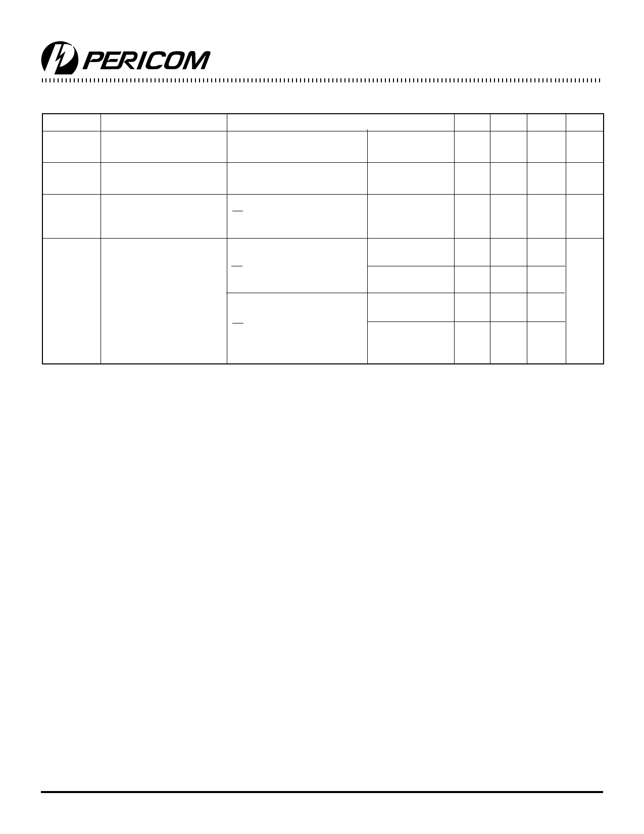
Power Supply Characteristics
Parameters Description
Test Conditions(1)
Min. Typ(2) Max. Units
ICC
Quiescent Power
Supply Current
VCC = Max.
∆ICC
Supply Current per
VCC = Max.
per Input @ TTL HIGH
VIN = GND or VCC
VIN = 3.4V(3)
0.1 500 µA
0.5 2.0 mA
ICCD
Supply Current per
VCC = Max., Outputs Open VIN = VCC
0.15
Input per MHx(4)
MR = Vcc, One Input Toggling VIN = GND
50% Duty Cycle
IC
Total Power Supply
VCC = Max., Outputs Open VIN = VCC
1.5
Current(6)
fCP = 10 MHZ, 50% Duty Cycle VIN = GND
MR = Vcc, 50% Duty Cycle VIN = 3.4V
2.0
One Bit toggling at fI = 5 MHZ VIN = GND
VCC = Max., Outputs Open VIN = VCC
3.8
fCP = 10 MHZ, 50% Duty Cycle VIN = GND
MR = VCC, 50% Duty Cycle VIN = 3.4V
Eight Bits toggling at
VIN = GND
6.0
fI = 2.5 MHZ, 50% Duty Cycle
Notes:
1. For Max. or Min. conditions, use appropriate value specified under Electrical Characteristics for the applicable device.
2. Typical values are at Vcc = 5.0V, +25°C ambient.
3. Per TTL driven input (VIN = 3.4V); all other inputs at Vcc or GND.
4. This parameter is not directly testable, but is derived for use in Total Power Supply Calculations.
5. Values for these conditions are examples of the Icc formula. These limits are guaranteed but not tested.
6. IC =IQUIESCENT + IINPUTS + IDYNAMIC
IC = ICC + ∆ICC DHNT + ICCD (fCP/2 + fINI)
ICC = Quiescent Current
∆ICC = Power Supply Current for a TTL High Input (VIN = 3.4V)
DH = Duty Cycle for TTL Inputs High
NT = Number of TTL Inputs at DH
ICCD = Dynamic Current Caused by an Input Transition Pair (HLH or LHL)
fCP = Clock Frequency for Register Devices (Zero for Non-Register Devices)
fI = Input Frequency
NI = Number of Inputs at fI
All currents are in milliamps and all frequencies are in megahertz.
0.25
3.5(5)
3.5(5)
7.3(5)
16.3(5)
mA/
MHz
mA
3
PS2013A 03/09/96
Share Link: 