CM1A12V Просмотр технического описания (PDF) - Panasonic Corporation
Номер в каталоге
Компоненты Описание
Список матч
CM1A12V Datasheet PDF : 5 Pages
| |||
CM
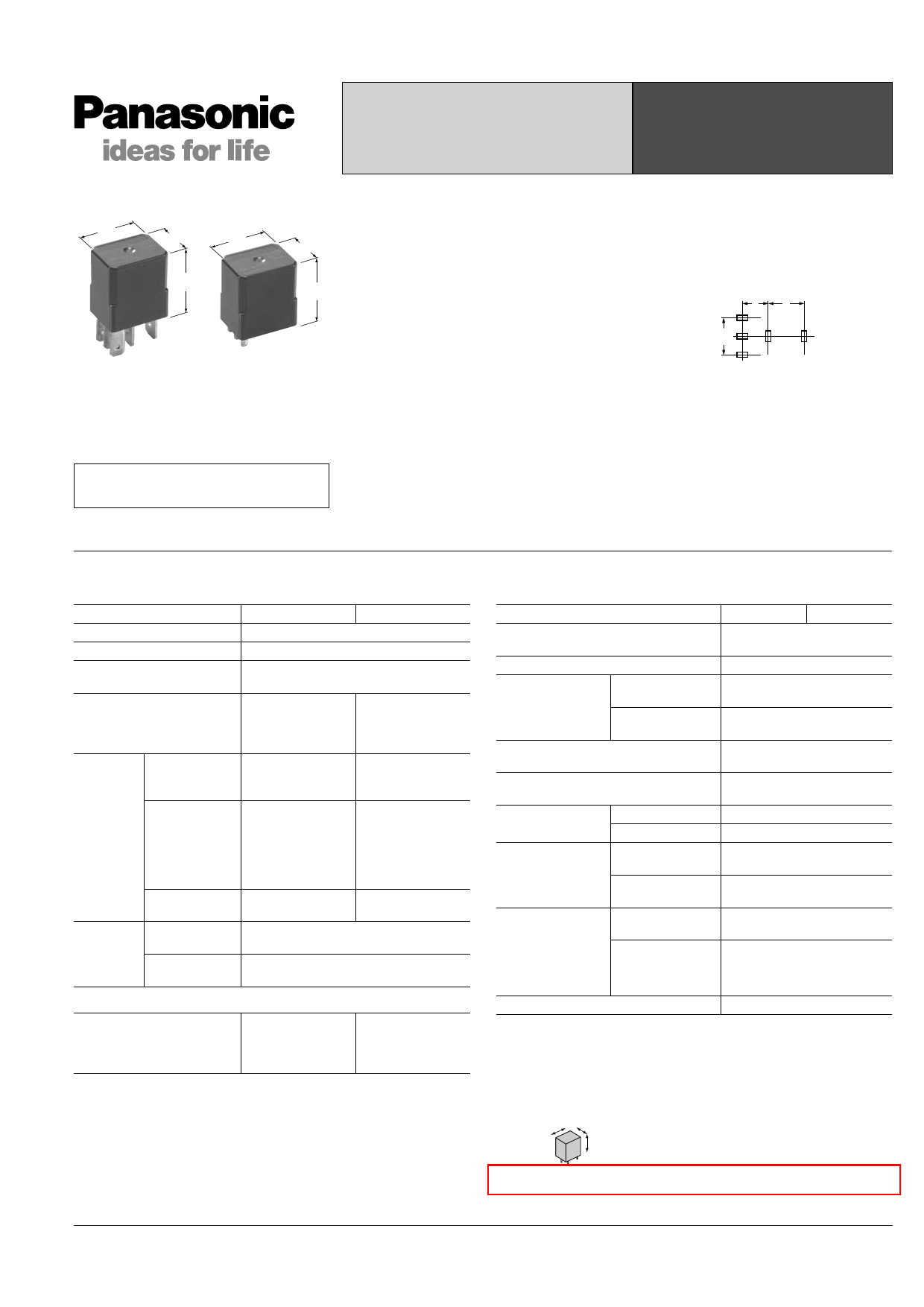
CM RELAYS AUTOMOTIVE MICRO-ISO
RELAY
20
.787
15
20
.591
.787
15
.591
22
.866
23
.906
mm inch
RoHS Directive compatibility information
http://www.nais-e.com/
FEATURES
• Micro-ISO type terminals
• Small size:
20 mm(L)×15 mm(W)×22 mm(H)
.787 inch(L)×.591 inch(L)×.866 inch(H)
• Wide line-up
PC board and Plug-in type, Resistor and
diode inside type.
24V DC type is also available.
• Compact and high-capacity 35A load
switching
N.O.: 35A 14V DC, N.C.: 20A 14V DC
(Sealed type)
Min. 5 × 10⁴
N.O.: 35A 14V DC, N.C.: 20A 14V DC
(Flux-resistant type)
Min. 105 *12V DC type
• Uses international standard ISO
terminal arrangement.
The ISO international standard terminal
arrangement is used.
(plug-in type)
6
8
.236 .315
9
.354
TYPICAL APPLICATIONS
• Fan motor
• Heater
• Head lump
• Air Compressor
• EPS
• ABS
• Blower fan
• Defogger, etc.
SPECIFICATIONS
Contact
Type
12 V coil voltage 24 V coil voltage
Arrangement
1 Form A, 1 Form C
Contact material
Ag alloy (Cadmium free)
Initial contact resistance (Initial)
(By voltage drop 6 V DC 1 A)
Typ. 2 mΩ
Contact voltage drop
Max. N.O.: 0.5 V
(at 35 A 14 V DC)
Max. N.C.: 0.3 V
(at 20 A 14 V DC)
Max. N.O.: 0.3 V
(at 15 A 28 V DC)
Max. N.C.: 0.2 V
(at 8 A 28 V DC)
Nominal
switching
capacity
N.O.: 35 A 14 V DC N.O.: 15 A 28 V DC
N.C.: 20 A 14 V DC N.C.: 8 A 28 V DC
Rating
(resistive
load)
Max. carrying
current
N.O.: 20 A
(14 V DC,
at 85°C 185°F)
N.C.: 10 A
(14 V DC,
at 85°C 185°F)
N.O.: 15 A
(28 V DC,
at 85°C 185°F)
N.C.: 8 A
(28 V DC,
at 85°C 185°F)
Min. switching
capacity#1
1 A 12 V DC
1 A 24 V DC
Expected
life
Mechanical
(at 120 cpm)
Electrical
(at rated load)
Min. 106
Flux-resistant type: Min. 105*1
Sealed type: Min. 5 × 10⁴
Coil
Nominal operating power
1.5 W
1.7 W
(with resistor
inside type)
1.8 W
2.0 W
(with resistor
inside type)
#1 This value can change due to the switching frequency, environmental conditions,
and desired reliability level, therefore it is recommended to check this with the
actual load.
Characteristics
Type
24V coil type 12V coil type
Max. operating speed
(at nominal switching capacity)
15 cpm
Initial insulation resistance*2
Min. 20 MΩ (at 500 V DC)
Initial breakdown
voltage*3
Between open
contacts
Between contacts
and coil
500 Vrms for 1 min.
500 Vrms for 1 min.
Operate time*4
(at nominal voltage) (at 20°C 85°F)
Max. 10 ms (initial)
Release time*4
(at nominal voltage) (at 20°C 85°F)
Max. 10 ms
Max. 15 ms (with diode) (initial)
Functional*5
Shock resistance
Destructive*6
Min. 200 m/s2 {20G}
Min. 1,000m/s2 {100G}
Vibration
resistance
Functional
Destructive*7
10 Hz to 500 Hz,
Min. 44.1 m/s2 {4.5 G}
10 Hz to 2,000 Hz,
Min. 44.1 m/s2 {4.5 G}
Conditions for
operation, trans-
port and storage*8
(Not freezing and
condensing at low
temperature)
Ambient temp.
Humidity
–40°C to + 85°C
–40°F to + 185°F
5% R.H. to 85% R.H.
Mass
Approx. 20g .71oz
Remarks
*1 At nominal switching capacity, operating frequency: 2s ON, 2s OFF
*2 Measurement at same location as “Initial breakdown voltage” section.
*3 Detection current: 10mA
*4 Excluding contact bounce time.
*5 Half-wave pulse of sine wave: 11 ms; detection time: 10 µs
*6 Half-wave pulse of sine wave: 6 ms
*7 Time of vibration for each direction; X, Y, Z direction: 4 hours
X
Y
Z
*8 Refer to Conditions for operation, transport and storage mentioned in AMBIENT
ENVIRONMENT.
Please inquire if you will be using the relay in a high temperature atmosphere.
All Rights Reserved © COPYRIGHT Matsushita Electric Works, Ltd.
Share Link: 