HD74HCT74A Просмотр технического описания (PDF) - Hitachi -> Renesas Electronics
Номер в каталоге
Компоненты Описание
Список матч
HD74HCT74A
Hitachi -> Renesas Electronics

HD74HCT74A Datasheet PDF : 10 Pages
| |||
HD74HCT74A
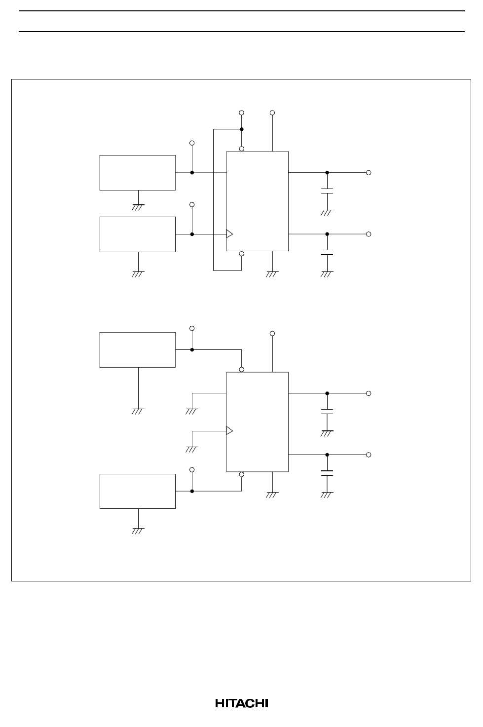
Test Circuit
1) fmax , t PLH ,t PHL (CLK → Q, Q)
Input
Pulse Generator
Zout = 50 Ω
Input
VCC VCC
PR
D
Q
Pulse Generator
Zout = 50 Ω
CLK
Q
CLR
2) tPLH ,t PHL (CLR or PR → Q, Q)
Input
Pulse Generator
Zout = 50 Ω
VCC
PR
D
Q
Input
Pulse Generator
Zout = 50 Ω
CLK
Q
CLR
Output Q
CL
Output Q
CL
Output Q
CL
Output Q
CL
Notes: 1. C L includes probe and jig capacitance.
2. Test is put into the each flip flops.
6
Share Link: