XC6204D22AML Просмотр технического описания (PDF) - TOREX SEMICONDUCTOR
Номер в каталоге
Компоненты Описание
Список матч
XC6204D22AML Datasheet PDF : 26 Pages
| |||
XC6204 Series
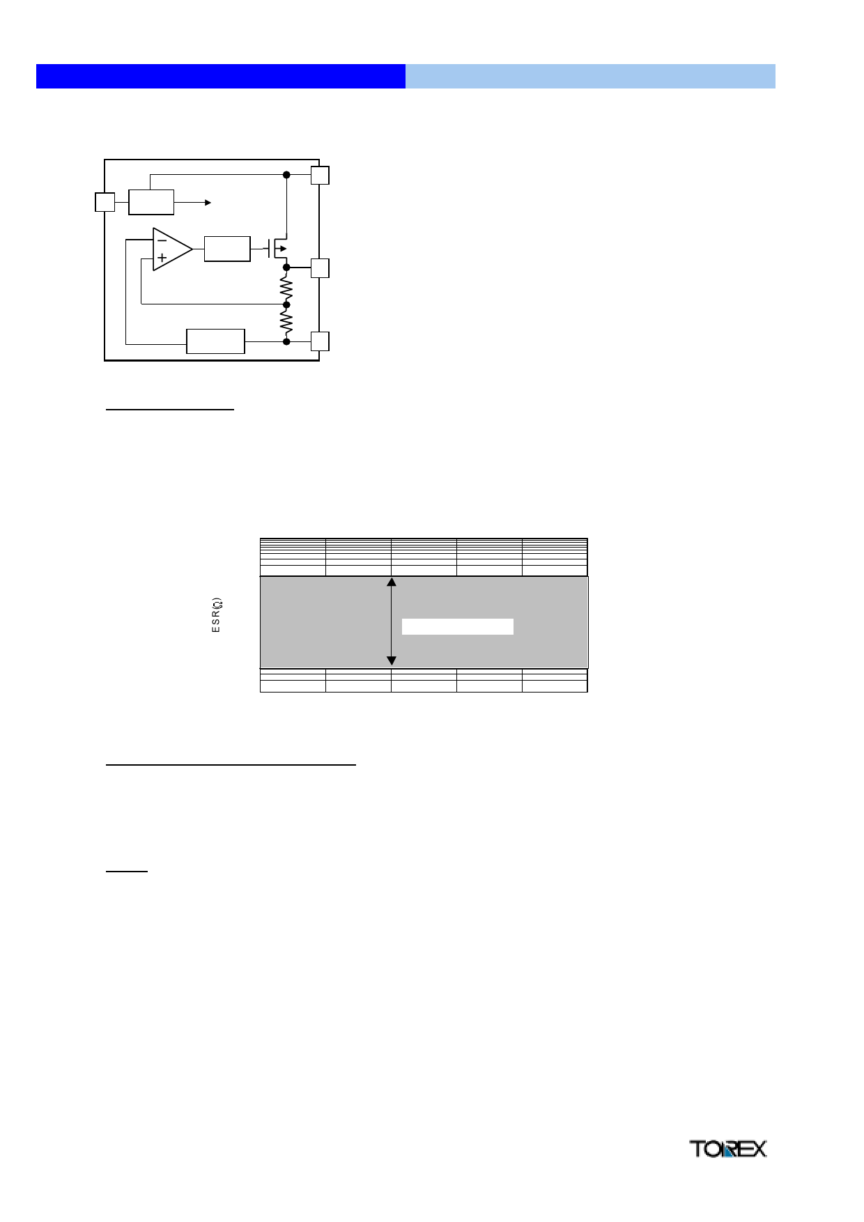
" Operational Explanation
CE
ON/OFF
Control
each circuit
Current
Limit
R2
R1
Voltage
Reference
VIN
VOUT
VSS
High Speed LDO Regulators
Output voltage control with the XC6204 series :
The voltage divided by resistors R1 & R2 is compared with
the internal reference voltage by the error amplifier.
The P-Channel MOSFET, which is connected to the VOUT
pin, is then driven by the subsequent output signal. The
ouput voltage at the VOUT pin is controlled & stabilised by
a system of negative feedback.
The current limit circuit and short protect circuit operate in
relation to the level of output current. Further, the IC's
internal circuitry can be shutdown via the CE pin's signal.
Low ESR Capacitors
With the XC6204 series, a stable output voltage is achievable even if used with low ESR capacitors as a phase compensation
circuit is built-in. In order to ensure the effectiveness of the phase compensation, we suggest that an output capacitor (CL) is
connected as close as possible to the output pin (VOUT) and the VSS pin. Please use an output capacitor with a capacitance
value of at least 1µF. Also, please connect an input capacitor (CIN) of 0.1µF between the VIN pin and the VSS pin in order to
ensure a stable power input.
100
Top r=2 5 OC
VIN = ~ 1 0 V,VO U T = 1 .8 ~ 6 .0 V
C IN = 1 .0 u F (c e ra m ic ),C L = 1 .0 u F(c e ra m ic )
10
1
S TA B L E R E G IO N
0.1
0.01
0
20
40
60
80
100
IO U T(m A )
Current Limiter, Short-Circuit Protection
The XC6204 series includes a combination of a fixed current limiter circuit & a foldback circuit which aid the operations of the
current limiter and circuit protection. When the load current reaches the current limit level, the fixed current limiter circuit operates
and output voltage drops. As a result of this drop in output voltage, the foldback circuit operates, output voltage drops further and
output current decreases (refer to the data on page 5). When the output pin is shorted, a current of about 60mA flows.
CE Pin
The IC's internal circuitry can be shutdown via the signal from the CE pin with the XC6204 series. In shutdown mode, output at the
VOUT pin will be pulled down to the VSS level via R1 & R2. The operational logic of the IC's CE pin is selectable (please refer to
the selection guide on page 2). Note that as the standard XC6204B type is ' High Active/No Pull Down' , operations will become
unstable with the CE pin open. Although the CE pin is equal to an inverter input with CMOS hysteresis, with either the pull-up or
pull-down options, the CE pin input current will increase when the IC is in operation.
We suggest that you use this IC with either a VIN voltage or a VSS voltage input at the CE pin. If this IC is used with the correct
specifications for the CE pin, the IC will operatenormally. However, supply current may increase as a result of through current in
the IC's internal circuitry if a voltage between 0.25V and 1.5V is input.
" Notes on Use
1. Please use this IC within the stated absolute maximum ratings. The IC is liable to malfunction should the ratings be exceeded.
2. Where wiring impedence is high, operations may become unstable due to noise and/or phase lag depending on output current.
Please strengthen VIN and VSS wiring in particular.
3. Please wire the input capacitor (CIN) and the output capacitor (CL) as close to the IC as possible.
6
Share Link: 