ARX2412 Просмотр технического описания (PDF) - Aeroflex Corporation
Номер в каталоге
Компоненты Описание
Список матч
ARX2412 Datasheet PDF : 7 Pages
| |||
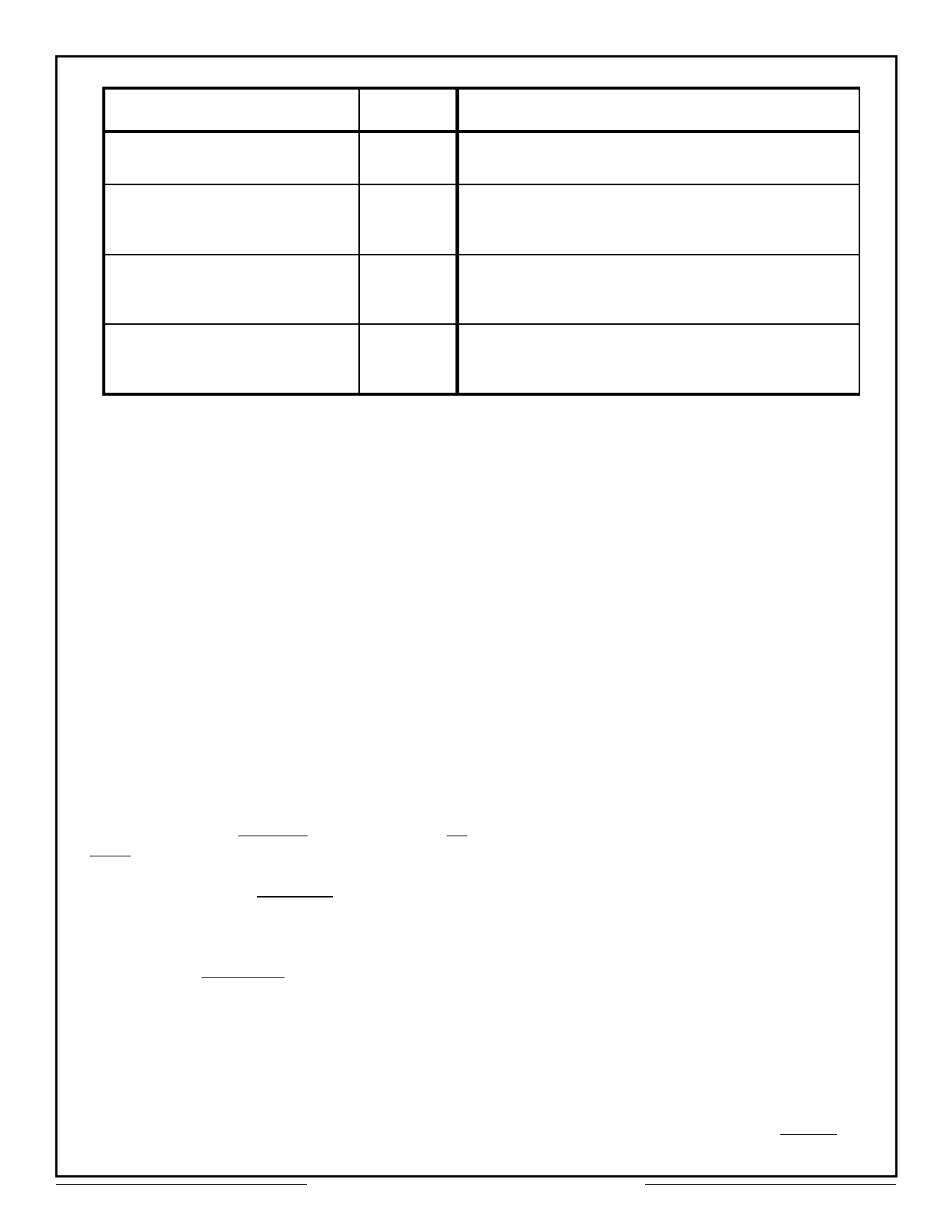
Parameter
External Clock
Oscillator Type (12MHz)
Power Supply Characteristics
Voltage Input
Current
Thermal Characteristics
Operating Current
Storage Current
Physical Characteristics
Weight
Size
Specifications
Units
Value
TTL
As per MIL-STD-1553 A/B long and short term
Vdc
+5.0 ±5%
mA
200 max
°C
-55 to +125 (Case Temperature)
°C
-55 to +150
oz
0.7 (20g) approx.
in.
1.7 x 1.1 x 0.2 (43 x 28 x 5.1 mm)
Theory of Operation
This section provides a detailed functional
description of the MIL-STD-1553A/B
Command/Response Manchester II converter
(hereinafter referred to as Converter) and is
intended for use with the timing diagrams shown
in Figures 2 and 3.
GENERAL
POWER ON CLEAR (POC): A logic "0" input
applied at turn-on initializes all of the internal
logic. This signal clears the encoder/decoder
internal counters and initializes the encoder and
decoder functions. This can also be used to abort
a transmission.
DECODER OPERATION
An seen in Figure 1, Functional Block Diagram,
the converter interfaces directly with the
MIL-STD-1553 transceiver by mans of four lines,
namely Tx DATA, Tx DATA, Rx DATA, and Rx
DATA. In the decode mode of operation, the
converter normally needs logic lows (OFF Mode)
on Rx DATA and Rx DATA. Whenever the
MIL-STD-1553 data bus is active, the
MIL-STD-1553 transceiver will output signals that
are similar to those illustrated in Figure 2 (Rx
DATA and Rx DATA) to the converter.
Approximately 5µsec after the converter has
detected the first transition change in, the Rx
DATA input line, the Received Busy output line will
activate from a low to high state and remain high
for 16µsec. During this period, the internal
Encoder/Decoder is shifting serial data out and
the information is being clocked into an internal 16
bit serial to parallel shift register. The Receiver
Busy line will go low after 16µsec, and will remain
low for 4µsec if another 20 bit word immediately
follows the first word. The second word will cause
Receiver Busy to go high for another 16µsec time
interval, This sequence continues until no
additional information is to be processed.
At approximately the same time as the first
Receiver Busy low to high transition, the Receiver
Sync Type line will go high if a command or status
sync field is detected by the internal decoder. It
too will remain high for 16µsec. If a data sync field
is detected by the decoder, the Receiver Sync
Type line will remain in the low state. During the
receiver busy time the decoder shifts serial data
out to the serial to parallel shift register,
regardless of whether the data is valid or not.
However, the stored data is not shifted into the
3-state output buffer unless a Valid Word
indication occurs. This signal is designated Valid
Word. Valid Word performs three functions within
the converter: strobes the 16 bit parallel word into
the 3-state output buffer, strobes the address
recognition function and indicates to the
subsystem user that a valid 16 bit word is now
ready to be processed. A high to low transition on
the Valid Word line will indicate the receipt of a
Valid Word.
The first five bits of a 16 bit command word
represent the terminal address. The bits are
decoded, shifted through the serial to parallel shift
register and compared to the five lines in the
address recognition register (own address, B0
(MSB) thru B4). If a command word is received,
and the own address lines and decoder remote
terminal address bits correspond, and Valid Word
occurs, then a Valid Address Signal (VU INT) will
Aeroflex Circuit Technology
2
SCD2412 REV C 10/19/98 Plainview NY (516) 694-6700
Share Link: 