UFB130FA40 Просмотр технического описания (PDF) - Vishay Semiconductors
Номер в каталоге
Компоненты Описание
Список матч
UFB130FA40 Datasheet PDF : 6 Pages
| |||
www.vishay.com
160
150
140
130
120
110
100
90
80
70
60
50
100
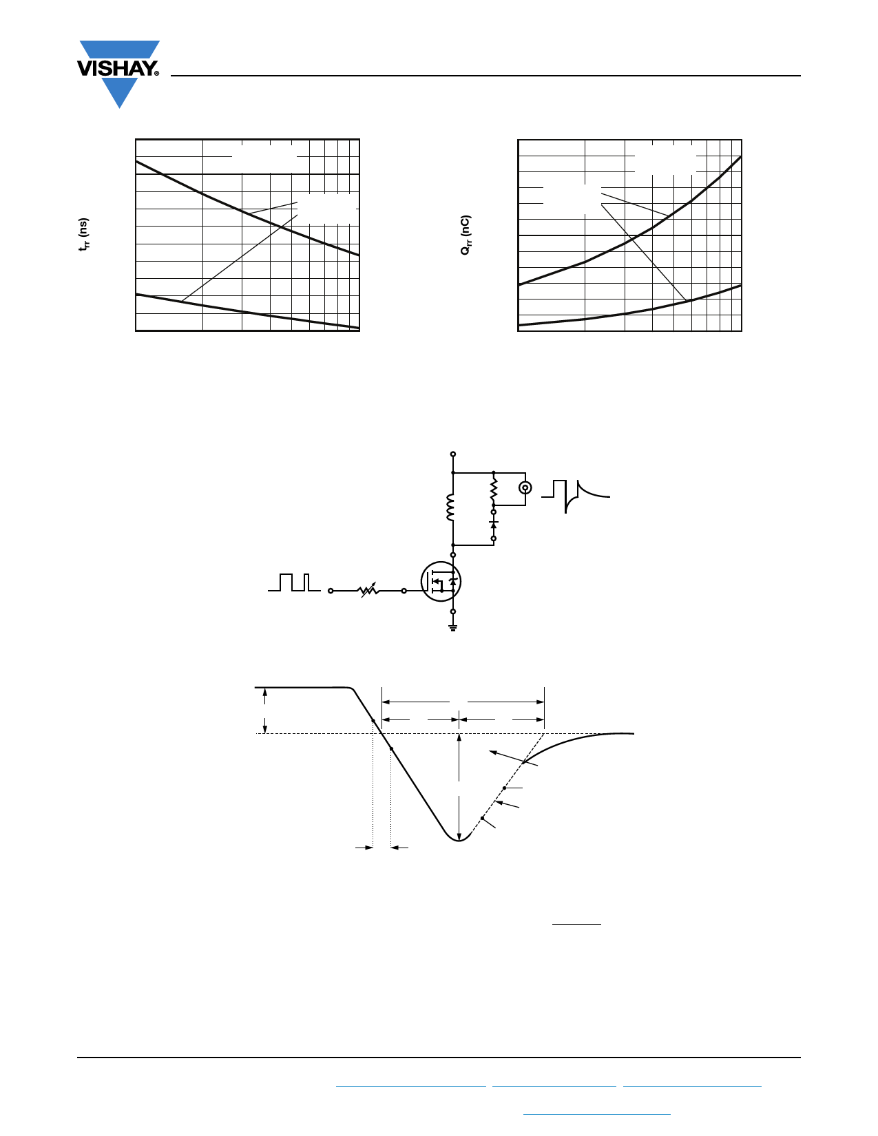
VRR = 200 V
IF = 50 A
TJ = 125 °C
TJ = 25 °C
dIF/dt (A/μs)
1000
Fig. 7 - Typical Reverse Recovery Time vs. dIF/dt
VS-UFB130FA40
Vishay Semiconductors
3050
2550
2050
1550
TJ = 125 °C
TJ = 25 °C
VRR = 200 V
IF = 50 A
1050
550
50
100
1000
dIF/dt (A/μs)
Fig. 8 - Typical Stored Charge vs. dIF/dt
VR = 200 V
L = 70 μH
0.01 Ω
D.U.T.
dIF/dt
adjust
G
D
IRFP250
S
Fig. 9 - Reverse Recovery Parameter Test Circuit
IF
0
(3)
trr
ta
tb
(2) IRRM
(4)
Qrr
0.5 IRRM
di(rec)M/dt (5)
0.75 IRRM
(1) diF/dt
(1) diF/dt - rate of change of current
through zero crossing
(4) Qrr - area under curve defined by trr
and IRRM
(2) IRRM - peak reverse recovery current
(3) trr - reverse recovery time measured
from zero crossing point of negative
going IF to point where a line passing
through 0.75 IRRM and 0.50 IRRM
extrapolated to zero current.
Qrr =
trr x IRRM
2
(5) di(rec)M/dt - peak rate of change of
current during tb portion of trr
Fig. 10 - Reverse Recovery Waveform and Definitions
Revision: 18-Sep-2018
4
Document Number: 93602
For technical questions within your region: DiodesAmericas@vishay.com, DiodesAsia@vishay.com, DiodesEurope@vishay.com
THIS DOCUMENT IS SUBJECT TO CHANGE WITHOUT NOTICE. THE PRODUCTS DESCRIBED HEREIN AND THIS DOCUMENT
ARE SUBJECT TO SPECIFIC DISCLAIMERS, SET FORTH AT www.vishay.com/doc?91000
Share Link: 