U2270B Просмотр технического описания (PDF) - Atmel Corporation
Номер в каталоге
Компоненты Описание
Список матч
U2270B Datasheet PDF : 18 Pages
| |||
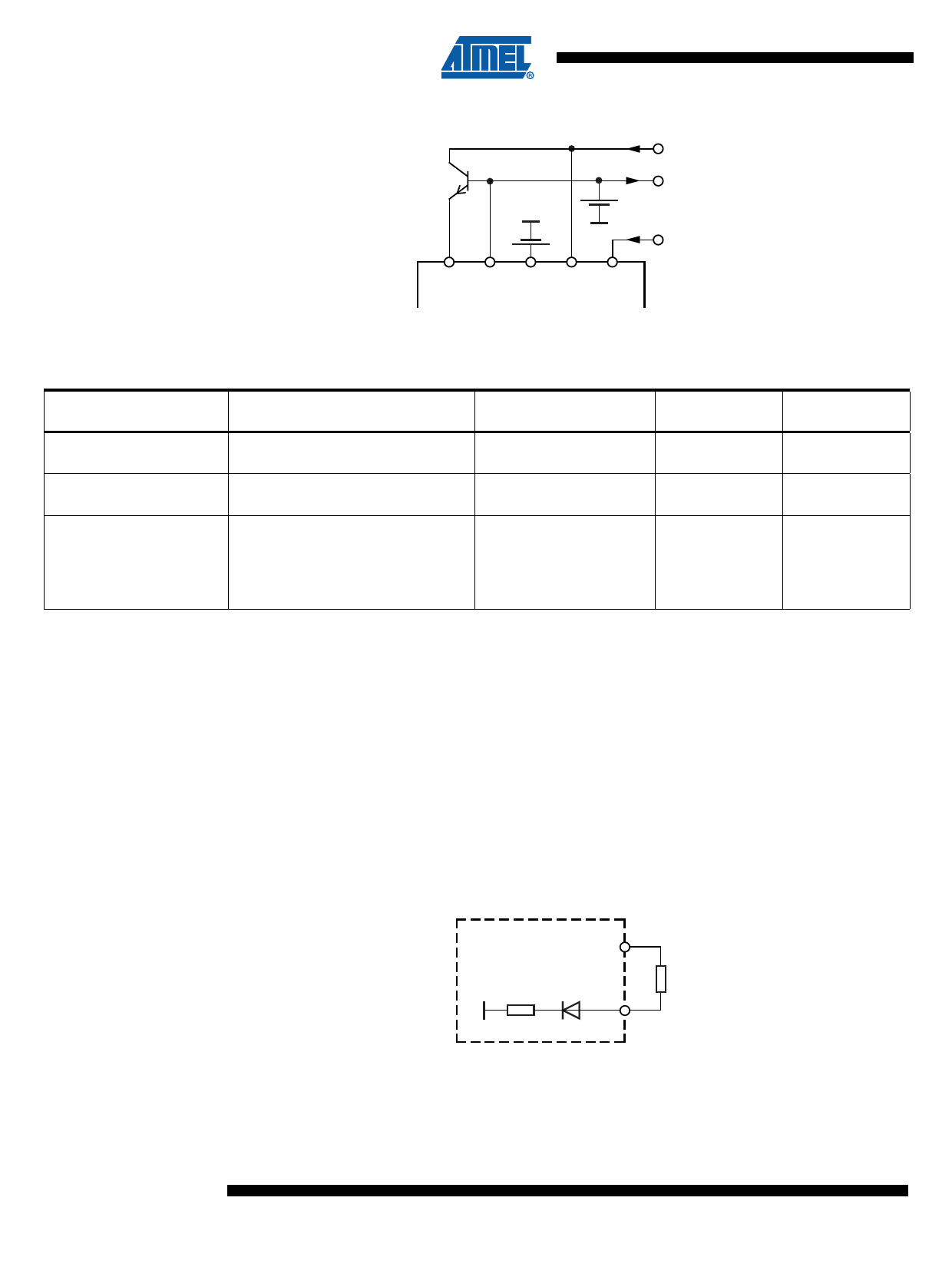
Figure 3-4. Battery Operation
7V to 16V
DVS VEXT VS VBatt Standby
Table 3-1. Characteristics of the Various Operation Modes
Operation Mode
One-rail operation
Two-rail operation
Battery-voltage operation
External Components Required
1 voltage regulator
1 capacitor
2 voltage regulators
2 capacitors
1 transistor
2 capacitors
Optional, for load dump protection:
1 resistor
1 capacitor
Supply-voltage Range
5V ±10%
5V ±10%
7V to 8V
6V to 16V
Driver Output
Voltage Swing
≈ 4V
6V to 7V
≈ 4V
Standby Mode
Available
No
No
Yes
3.3 Oscillator (Osc)
The frequency of the on-chip oscillator is controlled by a current fed into the RF input. An inte-
grated compensation circuit ensures a wide temperature range and a supply-voltage–
independent frequency which is selected by a fixed resistor between RF (pin 15) and VS (pin 14).
For 125 kHz, a resistor value of 110 kΩ is defined. For other frequencies, use the following
formula:
Rt[kΩ]=
---1---4----3---7---5----- – 5
f 0 [ kHz ]
This input can be used to adjust the frequency close to the resonance of the antenna. For more
details see Section “Applications” on page 10.
Figure 3-5. Equivalent Circuit of Pin RF
VS
2 kΩ
Rf
RF
6 U2270B
4684E–RFID–02/08
Share Link: 