IDT72261L20PFB Просмотр технического описания (PDF) - Integrated Device Technology
Номер в каталоге
Компоненты Описание
Список матч
IDT72261L20PFB Datasheet PDF : 30 Pages
| |||
IDT72261/72271 SyncFIFO™
16,384 x 9, 32,768 x 9
MILITARY AND COMMERCIAL TEMPERATURE RANGES
SERIAL ENABLE (SEN)
Serial Enable is (SEN) is an enable used only for serial
programming of the offset registers. The serial programming
method must be selected during Master Reset. SEN is always
used in conjunction with LD. When these lines are both LOW,
data at the SI input can be loaded into the input register one
bit for each LOW-to-HIGH transition of WCLK.
When SEN is HIGH, the programmable registers retains
the previous settings and no offsets are loaded.
SEN functions the same way in both IDT Standard and
FWFT modes.
OUTPUT ENABLE (OE)
When Output Enable (OE) is enabled (LOW), the parallel
output buffers receive data from the output register. When OE
is HIGH, the output data bus (Qn) goes into a high impedance
state.
LOAD (LD)
This is a dual purpose pin. During Master Reset, the state
of the Load line (LD) determines one of two default values (127
or 1023) for the PAE and PAF flags, along with the method by
which these flags can be programmed, parallel or serial. After
Master Reset, LD enables write operations to and read
operations from the registers. Only the offset loading method
currently selected can be used to write to the registers. Aside
from Master Reset, there is no other way change the loading
method. Registers can be read only in parallel; this can be
accomplished regardless of whether serial or the parallel
loading has been selected.
Associated with each of the programmable flags, PAE and
PAF, are two registers which can either be written to or read
from. Offset values contained in these registers determine
how many words need to be in the FIFO memory to switch a
partial flag. A LOW on LD during Master Reset selects a
default PAE offset value of 07FH ( a threshold 127 words from
the empty boundary), a default PAF offset value of 07FH (a
threshold 127 words from the full boundary), and parallel
loading of other offset values. A HIGH on LD during Master
Reset selects a default PAE offset value of 3FFH (a threshold
1023 words from the empty boundary), a default PAF offset
value of 3FFH (a threshold 1023 words form the full bound-
ary), and serial loading of other offset values.
The act of writing offsets (in parallel or serial) employs a
dedicated write offset register pointer. The act of reading
offsets employs a dedicated read offset register pointer. The
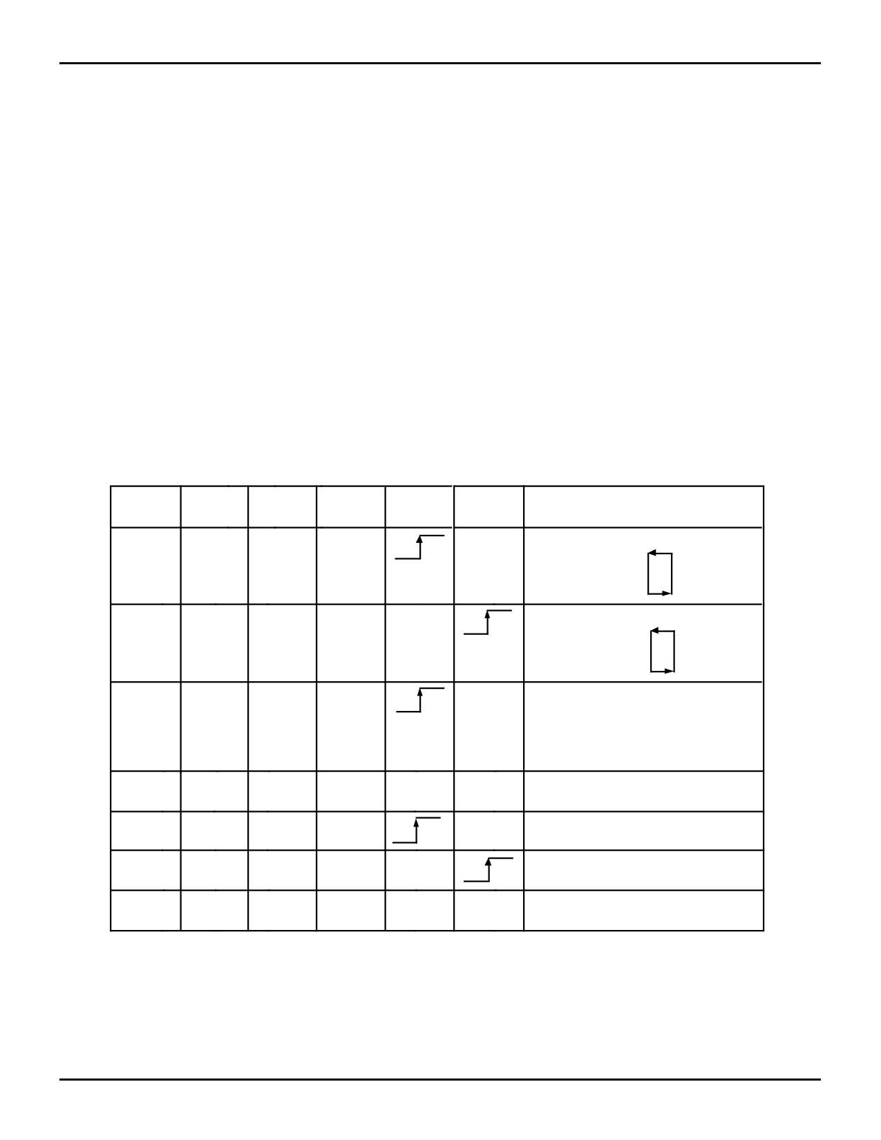
LD
WEN
REN
SEN
WCLK
RCLK
Selection
0
0
1
0
1
0
0
1
1
X
1
1
1
1
X
0
1
X
X
Parallel write to registers:
Empty Offset (LSB)
Empty Offset (MSB)
Full Offset (LSB)
Full Offset (MSB)
Parallel read from registers:
Empty Offset (LSB)
Empty Offset (MSB)
Full Offset (LSB)
Full Offset (MSB)
X
Serial shift into registers:
28 bits for the 72261
30 bits for the 72271
1 bit for each rising WCLK edge
Starting with Empty Offset (LSB)
Ending with Full Offset (MSB)
X
No Operation
1
0
X
X
X
Write Memory
1
X
0
X
X
Read Memory
1
1
1
X
X
X
No Operation
NOTES:
1. Only one of the two offset programming methods, serial or parallel, is available for use at any given time.
2. The programming method can only be selected at Master Reset.
3. Parallel reading of the offset registers is always permitted regardless of which programming method has been selected.
4. The programming sequence applies to both IDT Standard and FWFT modes.
Figure 2. Partial Flag Programming Sequence
3097 tbl 01
9
Share Link: 