TLP550 Просмотр технического описания (PDF) - Toshiba
Номер в каталоге
Компоненты Описание
Список матч
TLP550 Datasheet PDF : 7 Pages
| |||
TLP550
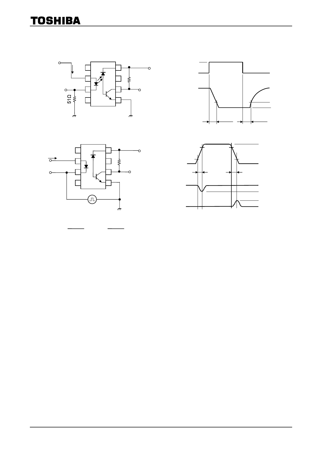
(Note 7) Switching time test circuit.
Pulse
input
IF
1
VCC=5V
8
IF
0
PW = 100μs
2
7
RL
Duty ratio = 1 / 10
IF monitor
3
6
VO
VO
4
5
Output
monitor
1.5V
5V
1.5V
VOL
tpHL
tpLH
(Note 8) Common mode transient immunity test circuit.
VCC=5V
1
8
IF
2
7
RL
3
6
VO
4
5
Output
monitor
VCM
Pulse gen
ZO=50Ω
160 (V)
CMH=
tf (μs)
160 (V)
, CML=
tf (μs)
VCM
tr
VO
(IF = 0mA)
VO
(IF = 16mA)
(Note 9) Maximum electrostatic discharge voltage for any pins: 100V (C = 200pF, R = 0)
90%
10%
tf
200V
0V
5V
2V
0.8V
VOL
4
2007-10-01
Share Link: 