TDA1575 Просмотр технического описания (PDF) - Philips Electronics
Номер в каталоге
Компоненты Описание
Список матч
TDA1575 Datasheet PDF : 16 Pages
| |||
Philips Semiconductors
FM front end circuit for
CENELEC EN 55020 applications
Preliminary specification
TDA1575T
APPLICATION INFORMATION
Operating characteristics
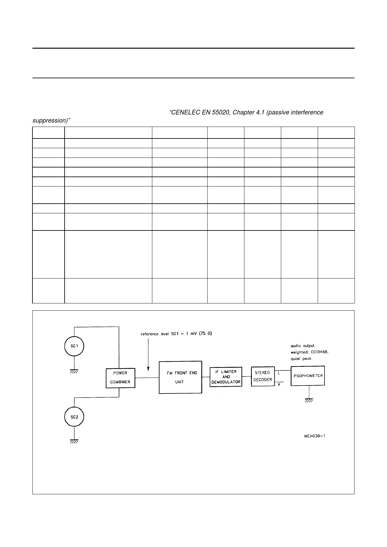
Measured in application circuit Fig.7, according to “CENELEC EN 55020, Chapter 4.1 (passive interference
suppression)”. Measurements are shown in Figs. 8 and 9.
SYMBOL
PARAMETER
VS
IS
fRF
Vtune
G
Vi ant
supply voltage
total supply current
tuning range of RF input
tuning voltage of RF input
gain (20 log VO IF / Vant)
input sensitivity
IR
RSS
image rejection
repeat spot suppression
DBS
double beat suppression
CBS
DBS1
DBS2
DBS3
continuous beat suppression
CONDITIONS
S/N = 26 dB;
Rant = 150 Ω
f = 98 MHz
f = 98 MHz;
Vi ant = 10 µV
f1 = 93 MHz;
f2 = 98 MHz
ftune = 88 MHz
ftune = 103 MHz
ftune = 90.15 MHz
f1 = 90 MHz;
f2 = 100.7 MHz
ftune = 95 MHz
MIN.
7
−
87.5
1
−
−
−
−
−
−
−
−
TYP.
8.5
37
−
−
43
2
64
89
81
80
85
90
MAX.
10
−
108
7
−
−
−
−
UNIT
V
mA
MHz
V
dB
µV
dB
dB
−
dB
−
dB
−
dB
−
dB
SG1: Wanted carrier; modulated with f = 1 kHz, ∆f = ±40 kHz (for audio reference)
SG2: Unwanted carrier; modulated with f = 1 kHz, FM: ∆f = ±40 kHz (in band) or AM: m = 80% (out of band)
increase level of SG2 until S/N = 26 dB w.r.t. wanted modulation (for car radio, home radio S/N = 40 dB)
Fig.5 Set-up for CENELEC EN 55020 passive interference measurements.
April 1993
7
Share Link: 