SPX1117T-L-2-5 Просмотр технического описания (PDF) - Signal Processing Technologies
Номер в каталоге
Компоненты Описание
Список матч
SPX1117T-L-2-5 Datasheet PDF : 16 Pages
| |||
Output Capacitor
To ensure the stability of the SPX1117, an
output capacitor of at least 2.2µF (tantalum or
ceramic) or 10µF (aluminum) is required. The
value may change based on the application
requirements of the output load or temperature
range. The value of ESR can vary based on the
type of capacitor used in the applications to
guarantee stability. The recommended value
for ESR is 0.5Ω or less. A larger value of
output capacitance (up to 100µF) can improve
the load transient response.
APPLICATION INFORMATION
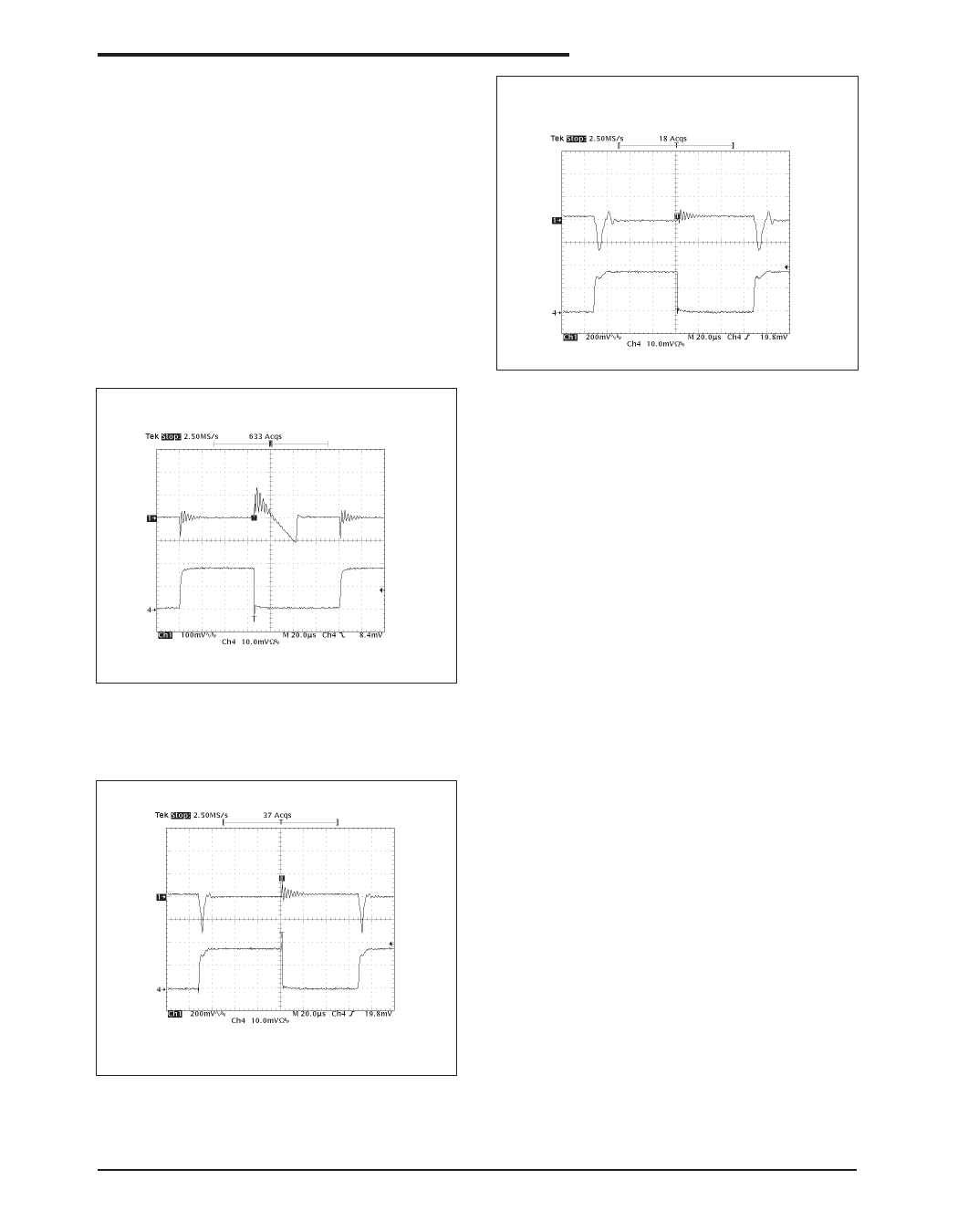
Figure 16. Load Step Response (0 to 800mA), Vin=3.3V,
Vout=1.8V, Cin=10µF, Cout=2.2µF, Ceramic; 1 = Vout,
4= Iload
Soldering Methods
The SPX1117 SOT-223 package is designed
to be compatible with infrared reflow or
vapor-phase reflow soldering techniques.
During soldering, the non-active or mildly
active fluxes may be used. The SPX1117 die
is attached to the heatsink lead which exits
opposite the input, output, and ground pins.
Hand soldering and wave soldering should be
avoided since these methods can cause
damage to the device with excessive thermal
gradients on the package. The SOT-223
recommended soldering method are as
follows: vapor phase reflow and infrared
reflow with the component preheated to within
65°C of the soldering temperature range.
Figure 17. Load Step Response (0 to 800mA), Vin=3.3V,
Vout=1.8V, Cin=10µF, Cout=2.2µF, OSCON; 1 = Vout,
4= Iload
Apr 20-07 Rev B
SPX1117 800mA Low Dropout Voltage Regulator
6
© 2007 Sipex Corporation
Share Link: 