ZCA8CPS12 Просмотр технического описания (PDF) - International Power DC Power Supplies
Номер в каталоге
Компоненты Описание
Список матч
ZCA8CPS12 Datasheet PDF : 4 Pages
| |||
OUTPUT VOLTAGE & CURRENT RATINGS
ZC8
Package
Style
Hot Swap
Chassis Mount
Hot Swap with Front Panel
IEC-320 Inlet with Switch
Chassis Mount with Front
Panel IEC-320 Inlet
with Switch
Maximum
Power
650 W
700 W
800 W
650 W
700 W
800 W
480 W
525 W
600 W
480 W
525 W
600 W
Output
Voltage
12.0 V
24.0 V
48.0 V
12.0 V
24.0 V
48.0 V
12.0 V
24.0 V
48.0 V
12.0 V
24.0 V
48.0 V
Maximum
Amps
54.2 A
29.2 A
16.7 A
54.2 A
29.2 A
16.7 A
40.0 A
21.9 A
12.5 A
40.0 A
21.9 A
12.5 A
Model
Number
ZCA8HPS12
ZCA8HPS24
ZCA8HPS48
ZCA8CPS12
ZCA8CPS24
ZCA8CPS48
ZCA8HPS12C
ZCA8HPS24C
ZCA8HPS48C
ZCA8CPS12C
ZCA8CPS24C
ZCA8CPS48C
Notes
1 Part numbers in bold type are standard stock models, all others including options below are build to order.
2. Standard airflow is front to rear. For optional reverse airflow add suffix R to the part number. Derate rear input models 20%, front panel IEC-320 inlet
models 16.6%.
3. Optional I2 C function by adding the suffix I to the part number.
4. Optional reverse airflow and I2C function by adding the suffix M to the part number. Derate rear connector models 20%, front panel IEC-320 inlet
models 16.6%.
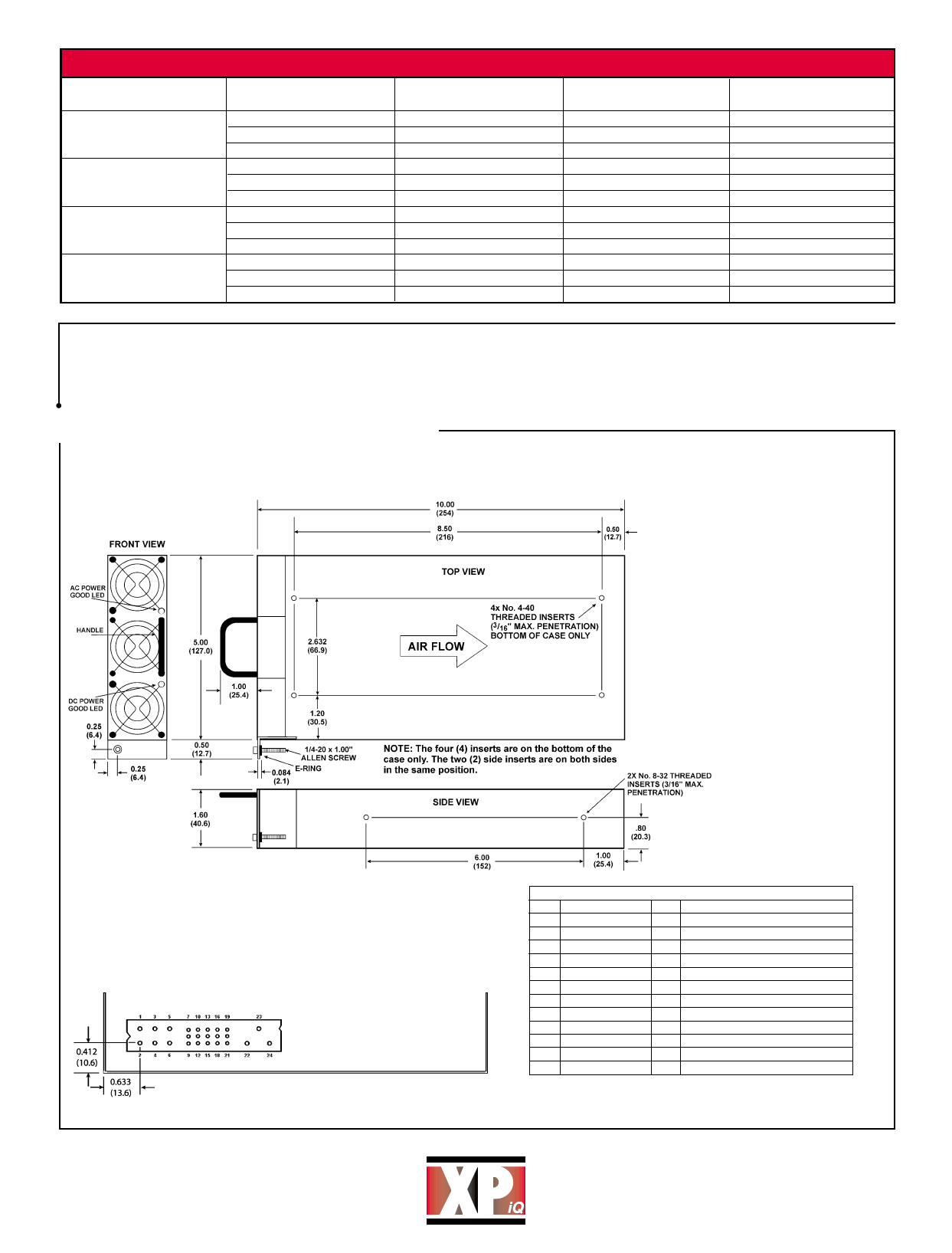
Mechanical Details - Power Supply
Notes:
1. Hot swap models are illustrated in
the mechanical drawing.
Chassis mount models do not have
handle or mounting bracket with
thumb-screw.
2. For unit to operate, Enable Pin
(Pin 7) must be at logic LO or
shorted to Pin 9.
3. For proper operation all output
pins (1-3) should be connected
together, Also, all returns pins (4-6)
should be connected together.
4. Pins 11, 12, 14, 17 & 19 functions
are only present with I2C option.
5. Dimensions shown in inches (mm).
6. Vertical blackplane mounting may
not allow for sufficient airflow.
Horizantal backplane, or additional
spacing with a vertical backplane is
recommended.
Connector: Positronics PCIB24W9M400A1
Mate: PCIB24W9F400A1
Note: Output Connector is flush with the end of the case
±0.040 (1.02).
Pin Function
1
+V Out
2
+V Out
3
+V Out
4 V Return
5 V Return
6 V Return
7
Enable
8
+Sense
9
-Sense
10
Inhibit
11 Spare/SDA
12 Spare/SCL
Pin Connections
Pin
Function
13 Module Present
14 DC Power Good/Add GA1
15 AC Power Fail
16 V Trim
17 Overtemp. Warning/Add GA0
18 Current Share
19 Current Monitor/Add GA2
20 +5V Standby
21 Standby Return
22 Chassis Ground
23 AC Line
24 AC Neutral
www.XPiQ.com
PH: 508 429.9883
FAX: 800 226.2100
Email: sales@xpiq.com
Holliston, MA 01746 USA
Share Link: 