CS8413 Просмотр технического описания (PDF) - Cirrus Logic
Номер в каталоге
Компоненты Описание
Список матч
CS8413 Datasheet PDF : 38 Pages
| |||
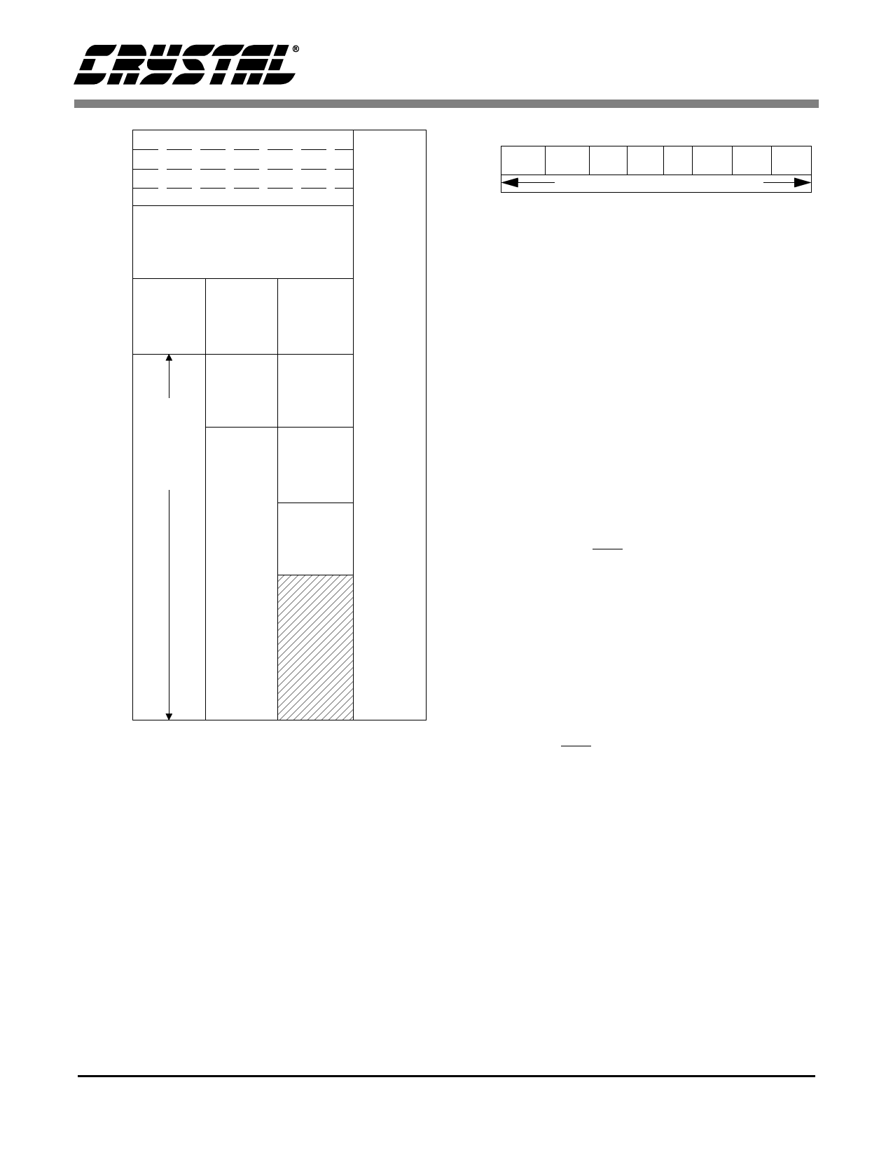
CS8413 CS8414
0
Status 1 / IEnable 1
1
Status 2 / IEnable 2
2
Control Register 1
3
Control Register 2
4
5
User Data
6
7
8
9 1st Four 1st Four
Bytes of Bytes of
A C. S. Data C. S. Data
B
1st Four
Bytes of
Left C. S.
Data
U
N
D
E
F
C
I
AD
DE
D
R
E
F
10
Last
20 Bytes
Channel
C. S.
Data
Left
C. S.
Data
1st Four
N
E
D
S 11 Status
Bytes of
S 12 Data
Right
13
C. S. Data
14
15
Auxiliary
Right
16
Data
C. S.
Data
17
18
19
1A
1B
1C
1D
1E
1F
0
1
2
3
Memory Mode
Figure 5. CS8413 Buffer Memory Map
pulses are generated the first time that condition oc-
curs. If the status register is not read, further in-
stances of that same condition will not generate
another interrupt. ERF is the error flag bit and is set
when the ERF pin goes high. It is an OR’ing of the
errors listed in status register 2, bits 0 through 4,
AND’ed with their associated interrupt enable bits
in IEnable register 2.
SLIP is only valid when the audio port is in slave
mode (FSYNC and SCK are inputs to the CS8413).
This flag is set when an audio sample is dropped or
X:00
SR1.
IER1.
7
CSDIF/
CRC2
6
5
4
3
2
1
0
CRCE/ CCHG SLIP ERF FLAG2 FLAG1 FLAG0
CRC1
INTERRUPT ENABLE BITS FOR ABOVE
SR1:
CSDIF:
CRC2:
CRCE:
CRC1:
CCHG:
SLIP:
ERF:
FLAG2:
FLAG1:
FLAG0:
CS different between sub-frames. Buffer modes 0 & 1
CRC Error - sub-frame 2. Buffer mode 2 only.
CRC Error - selected sub-frame. Buffer modes 0 & 1
CRC Error - sub-frame 1. Buffer mode 2 only.
Channel Status changed
Slipped an audio sample
Error Flag. ORing of all errors in SR2.
High for first four bytes of channel status
Memory mode dependent - See Figure 11.
High for last two bytes of user data.
IER1: Enables the corresponding bit in SR1.
A “1” enables the interrupt. A “0” masks the interrupt.
Figure 6. Status/IEnable Register 1
reread because the audio data output from the part
is at a different frequency than the data received
from the transmission line. CCHG is set when any
bit in channel status bytes 0 through 3, stored in the
buffer, changes from one block to the next. In buff-
er modes 0 and 1, only one channel of channel sta-
tus data is buffered, so CCHG is only affected by
that channel. (CS2/CS1 in CR1 selects which chan-
nel is buffered.) In buffer mode 2 both channels are
buffered, so both channels affect CCHG. This bit is
updated after each byte (0 to 3) is written to the
buffer. The two most significant bits in SR1,
CRCE/CRC1 and CSDIF/CRC2, are dual function
flags. In buffer modes 0 and 1, they are CRCE and
CSDIF, and in buffer mode 2, they are CRC1 and
CRC2. In buffer modes 0 and 1, the channel select-
ed by the CS2/CS1 bit is stored in RAM and CRCE
indicates that a CRC error occurred in that channel.
CSDIF is set if there is any difference between the
channel status bits of each channel. In buffer mode
2 channel status from both channels is buffered,
with CRC1 indicating a CRC error in channel 1 and
CRC2 indicating a CRC error in channel 2. CRCE,
CRC1, and CRC2 are updated at the block bound-
ary. Block boundary violations also cause CRC1,2
or CRCE to be set.
IEnable register 1, which occupies the same ad-
dress space as status register 1, contains interrupt
enable bits for all conditions in status register 1. A
“1” in a bit location enables the same bit location in
10
DS240F1
Share Link: 