SI2401 Просмотр технического описания (PDF) - Silicon Laboratories
Номер в каталоге
Компоненты Описание
Список матч
SI2401 Datasheet PDF : 72 Pages
| |||
Si2401/Si3008
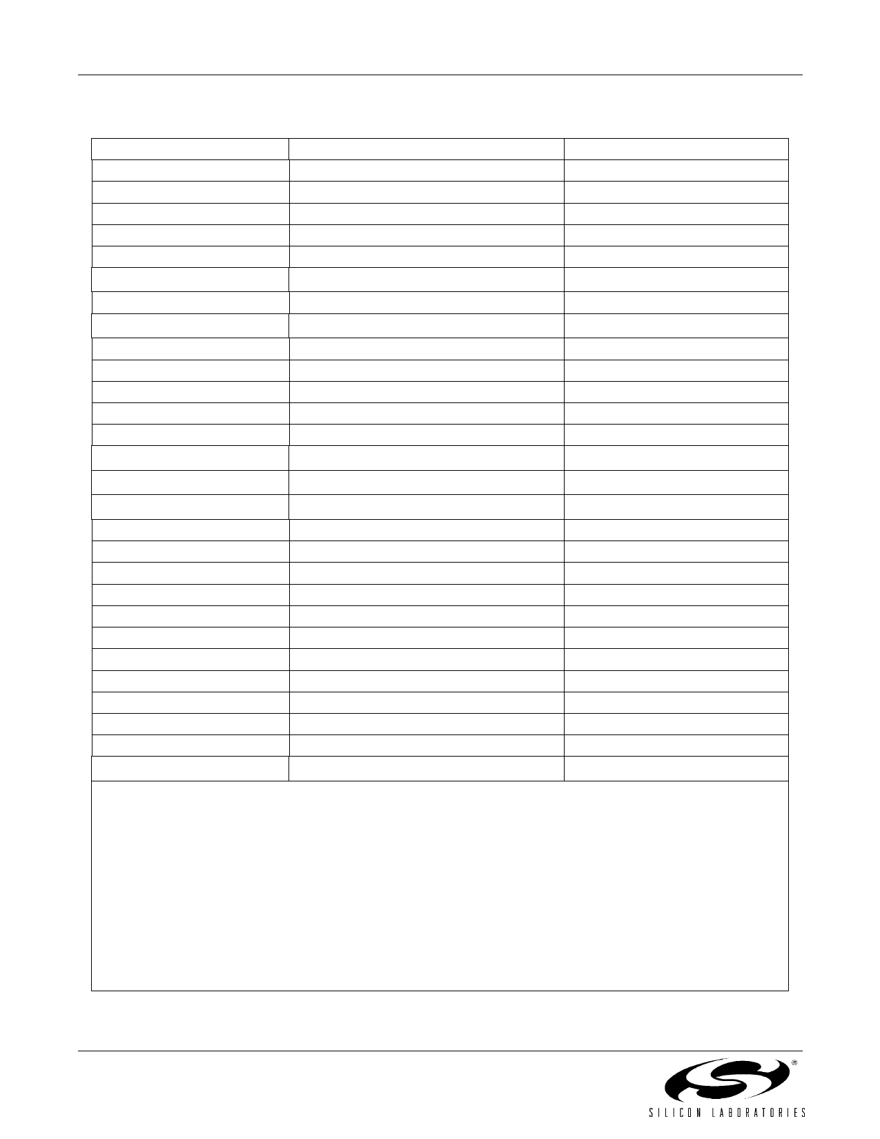
3. Bill of Materials: Si2401/08 Chipset
Component
Value
Supplier(s)
C1, C2
33 pF, Y2, X7R, ±20%
Panasonic, Murata, Vishay
C3
10 nF, 250 V, X7R, ±20%
Venkel, SMEC
C4
1.0 µF, 25 V, X7R, ±20%
Venkel, SMEC
C5, C50
0.1 µF, 16 V, X7R, ±20%
Venkel, SMEC
C8, C9
C111
C40, C412
680 pF, Y2, X7R, ±10%
330 pF, 50 V, X7R, ±20%
33 pF, 16 V, NPO, ±5%
Panasonic, Murata, Vishay
Venkel, SMEC
Venkel, SMEC
C51
D1, D23
0.22 µF, 16 V, X7R, ±20%
Dual Diode, 225 mA, 300 V, CMPD2004S
Venkel, SMEC
Central Semiconductor
FB1, FB2
Ferrite Bead, BLM18AG601SN1B
Murata
Q1, Q3
NPN, 300 V, MMBTA42
OnSemi, Fairchild
Q2
PNP, 300 V, MMBTA92
OnSemi, Fairchild
RV1
Sidactor, 275 V, 100 A
Teccor, Protek, ST Micro
R14
205 Ω, 1 W, ±1%
Venkel, SMEC, Panasonic
R25
243 Ω, 1 W, ±1%
Venkel, SMEC, Panasonic
R4
3.9 kΩ, 1/16 W, ±5%
Venkel, SMEC, Panasonic
R5, R6
R7, R86
100 kΩ, 1/16 W, ±5%
10 MΩ, 1/16 W, ±5%
Venkel, SMEC, Panasonic
Venkel, SMEC, Panasonic
R10
R12, R13
R15, R167
1 kΩ, 1/16 W, ±5%
56 Ω, 1/16 W, ±1%
0 Ω, 1/16 W
Venkel, SMEC, Panasonic
Venkel, SMEC, Panasonic
Venkel, SMEC, Panasonic
R18
1.5 MΩ, 1/16 W, ±5%
Venkel, SMEC, Panasonic
R19
R20, R211
180 kΩ, 1/16 W, ±5%
3 MΩ, 1/16 W, ±5%
Venkel, SMEC, Panasonic
Venkel, SMEC, Panasonic
U1
Si2401
Silicon Labs
U2
Y12,8
Z19
Si3008
4.9152 MHz, 20 pF, 100 ppm, 150 Ω ESR
Dual Zener Diode, 20 V, 1/4 W
Silicon Labs
ECS Inc., Siward
Vishay
Notes:
1. In applications that do not require caller ID, C11, R20, and R21 can be removed.
2. In STB applications, C40, C41, and Y1 can be removed by using the 27 MHz clock input feature.
3. Several diode bridge configurations are acceptable. For example, a single DF04S or four 1N4004 diodes may be
used.
4. Three parallel 619 Ω, 1/4 W, resistors may be used instead of R1.
5. Three parallel 732 Ω, 1/4 W, resistors may be used instead of R2.
6. The package size on R7 and R8 must be at least 0805.
7. Murata BLM18AG601SN1 may be substituted for R15–R16 (0 Ω) to decrease emissions.
8. To ensure compliance with ITU specifications, frequency tolerance must be less than 100 ppm including initial
accuracy, 5-year aging, 0 to 70 °C, and capacitive loading. 50 ppm initial accuracy crystals typically satisfy this
requirement.
9. Two series Zener diodes may be used instead of Z1.
10
Rev. 1.1
Share Link: 