RF2919 Просмотр технического описания (PDF) - RF Micro Devices
Номер в каталоге
Компоненты Описание
Список матч
RF2919 Datasheet PDF : 18 Pages
| |||
RF2919
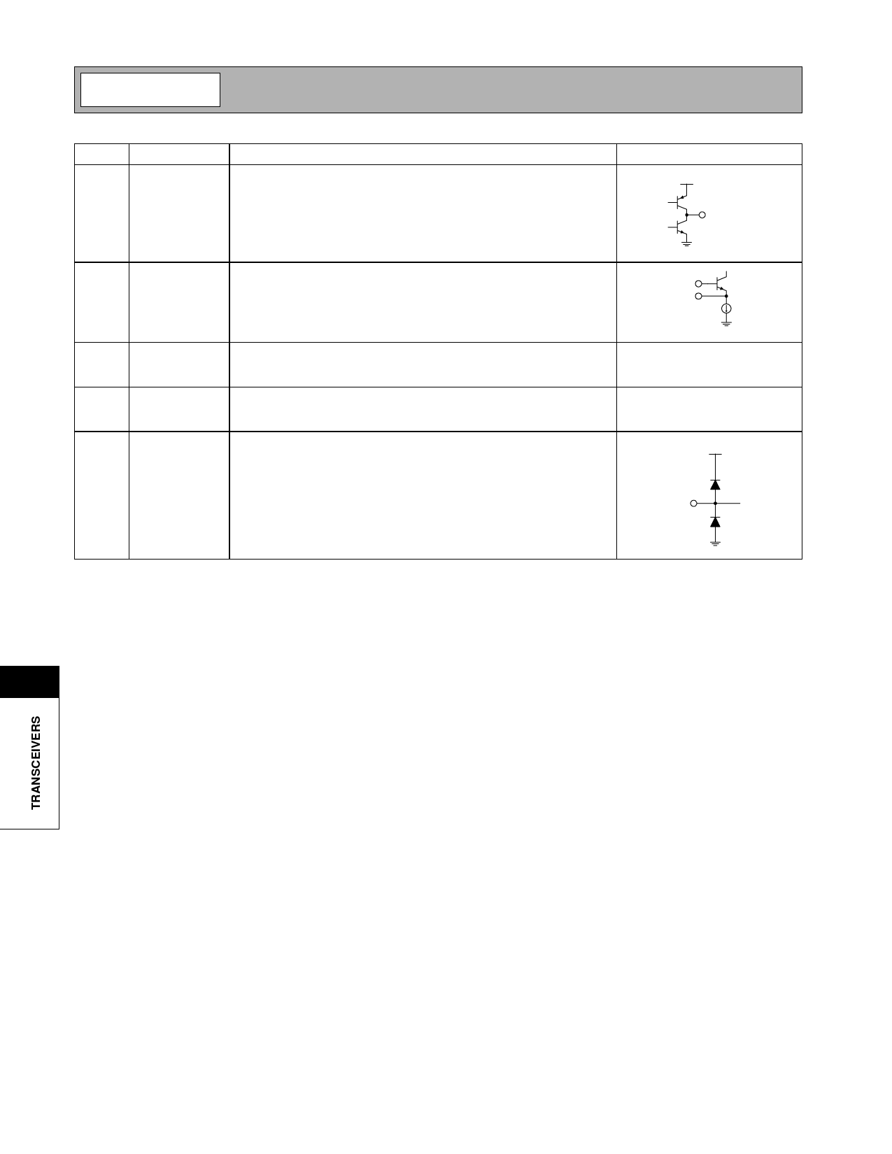
Pin Function Description
Interface Schematic
29
LOOP FLT Output of the charge pump, and input to the VCO control. An RC net-
work from this pin to ground is used to establish the PLL bandwidth.
VCC
LOOP FLT
30
OSC B
This pin is connected directly to the reference oscillator transistor base.
The intended reference oscillator configuration is a modified Colpitts. A
100pF capacitor should be connected between pin 30 and pin 31.
OSC B
OSC E
31
OSC E
This pin is connected directly to the emitter of the reference oscillator See pin 30.
transistor. A 100pF capacitor should be connected from this pin to
ground.
32
PD
This pin is used to power up or down the RF2919. A logic high (PWR
DWN >2.0 V) powers up the receiver and PLL. A logic low (PWR DWN
<1.0 V) powers down circuit to standby mode.
ESD
This diode structure is used to provide electrostatic discharge protec-
tion to 3kV using the Human body model. The following pins are pro-
VCC
tected: 1, 3, 5, 7-19, 21-24, 27-31.
11
11-148
Rev A12 001113
Share Link: 