RT9271 Просмотр технического описания (PDF) - Richtek Technology
Номер в каталоге
Компоненты Описание
Список матч
RT9271 Datasheet PDF : 15 Pages
| |||
RT9271
Application Information
LED Current Control
The RT9271 regulates the LED current by setting the current
sense resistor (R2) connecting to feedback and ground.
The internal feedback reference voltage is 0.25V. The LED
current can be set from following equation easily.
R2 = 0.25V ILED
In order to have an accurate LED current, precision resistors
are preferred (1% is recommended). The table for R2
selection is shown below.
R2 Resistor Value Selection
ILED (mA)
5
R2 (Ω)
49.9
10
24.9
12
21
15
16.5
20
12.4
Recommended Inductance and Rectifier (for Li-Ion cell)
Condition
2 WLEDs
3 WLEDs
Inductance (H) Schottky Diode
4.7u~10u
SS0520
4.7u~10u
SS0520
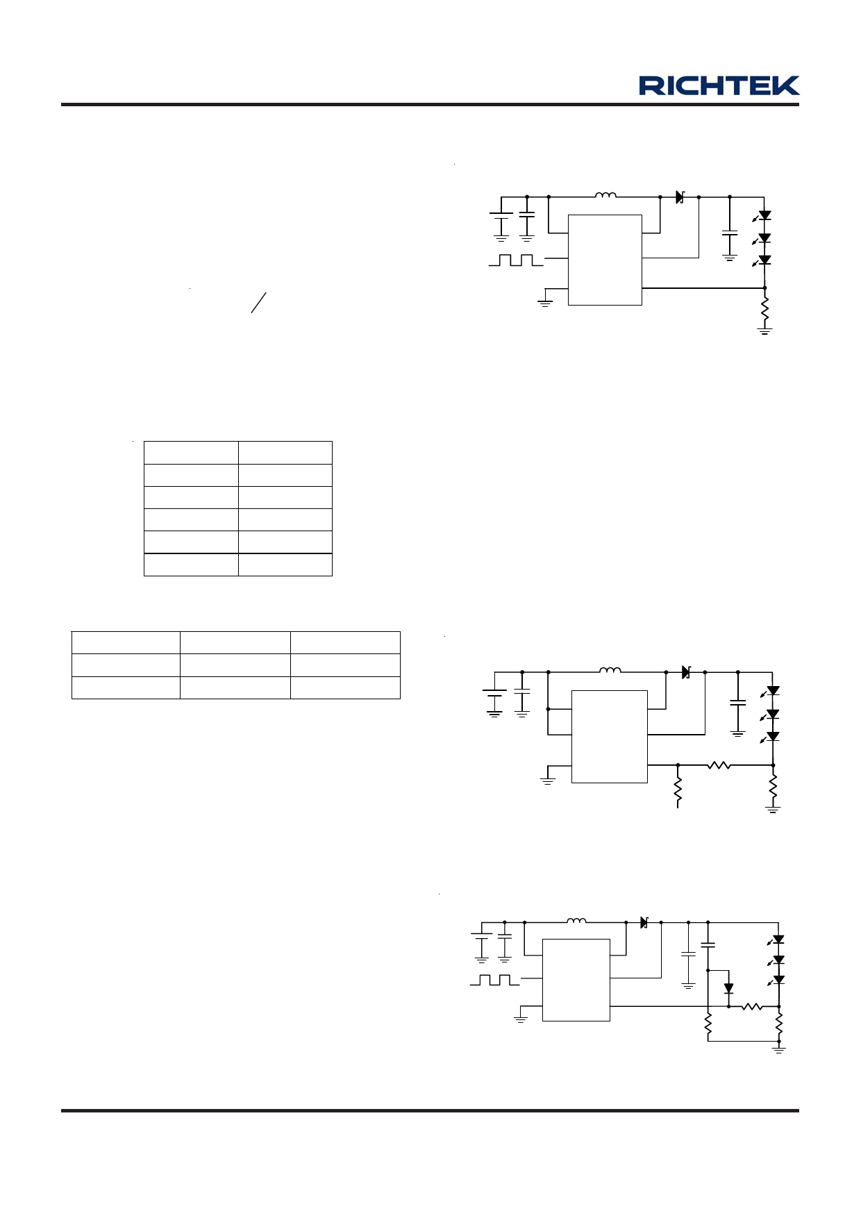
Dimming Control
a. Using a PWM Signal to EN Pin
For controlling the LED brightness, the RT9271 can perform
the dimming control by applying a PWM signal to EN pin.
The average LED current is proportional to the PWM signal
duty cycle. The magnitude of the PWM signal should be
higher than the maximum enable voltage of EN pin, in order
to let the dimming control perform correctly.
C1
VIN
1uF
2.4 to 6V
PWM signal
LX
10uH
D1
SS0520
D2
VCC
EN
LX
OVP
C3
D3
1uF
D4
GND FB
R2
RT9271
12
Figure 4. PWM Dimming Control Using the EN Pin
b. Using a DC Voltage
Using a variable DC voltage to adjust the brightness is a
popular method in some applications. The dimming control
using a DC voltage circuit is shown in Figure 5. According
to the Superposition Theorem, as the DC voltage increases,
the voltage contributed to VFB increases and the voltage
drop on R2 decreases, i.e. the LED current decreases.
For example, if the VDC range is from 0V to 2.8V, the
selection of resistors in Figure 5 sets dimming control of
LED current from 20mA to 0mA.
C1
VIN
1uF
2.4 to 6V
LX
10uH
D1
SS0520
C3
VCC
LX
1uF
EN
OVP
GND FB
RT9271
R3
6.8k
R4
82k
VDC Dimmimg
0 to 2.8V
D2
D3
D4
R2
12
Figure 5. Dimming Control Using a DC Voltage
C1
VIN
1uF
2.4 to 6V
LX
10uH
D1
SS0520
D2
C6
PWM signal
VCC
EN
LX
OVP
GND FB
C3
10nF
D3
1uF
D4
R5
1k
RT9271
R6
R2
10k
12
Figure 6. Recommended Soft-Start Circuit
www.richtek.com
10
DS9271-13 March 2007
Share Link: 