RT9173 Просмотр технического описания (PDF) - Richtek Technology
Номер в каталоге
Компоненты Описание
Список матч
RT9173 Datasheet PDF : 13 Pages
| |||
RT9173/A
Molding Compound
Lead Frame
Die
Case Point
Die Pad
Ambient
Molding Compound
Gold Wire
Die Pad
Lead Frame
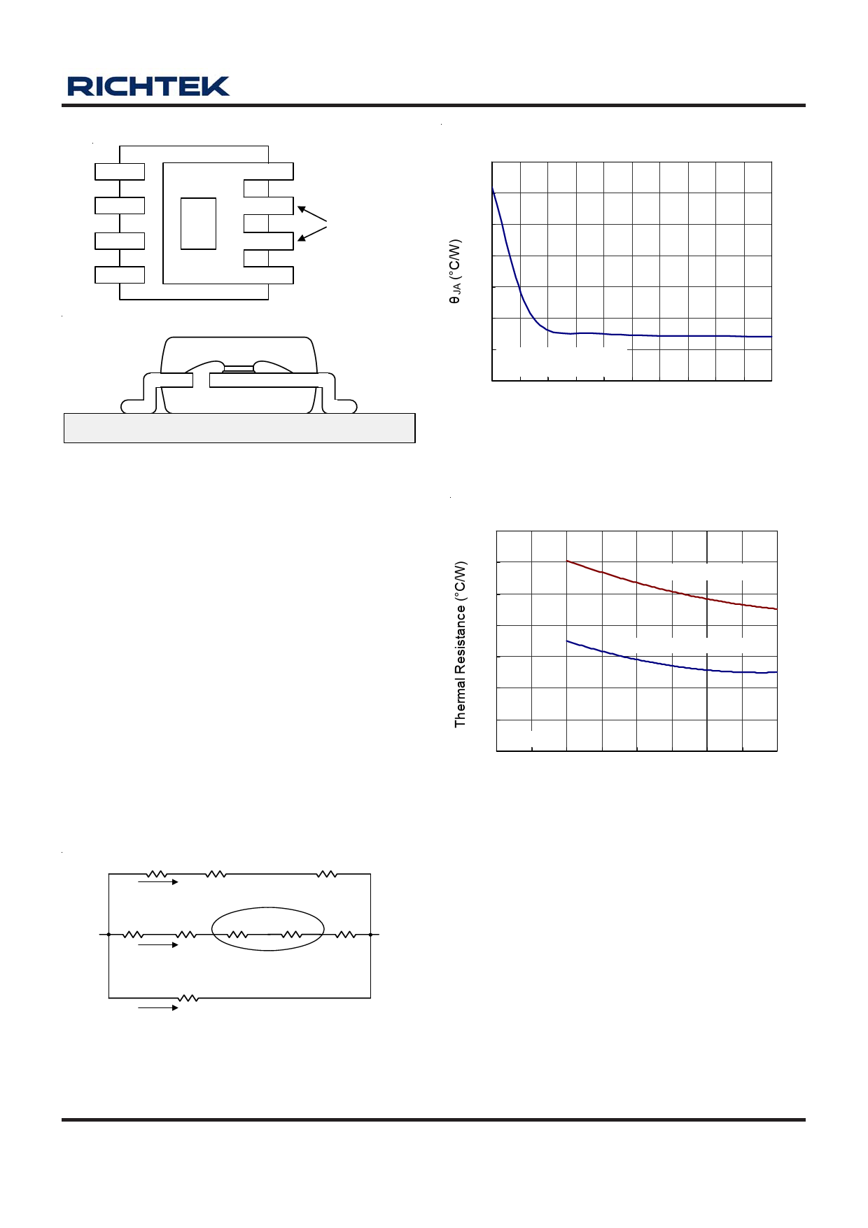
Figure 7. The Package Section Drawing of RT9173/A
SOP-8 Package
The thermal resistance θJA of IC package is determined by
the package design and the PCB design. However, the
package design has been decided. If possible, it's useful
to increase thermal performance by the PCB design. The
thermal resistance can be decreased efficiently by adding
copper under the main path of thermal flow on the package.
The maximum power dissipation depends on operating
ambient temperature for fixed TJ(MAX) and thermal
resistance θJA. For RT9173/A package, the Figure 9 and
the Figure 10 show the thermal resistance θJA vs. copper
area of SOP-8 and TO-263-5 packages on single layer
(1S) and 4-layer (2S2P) thermal test board at TA = 25°C,
PCB copper thickness = 2oz.
Junction
RGOLD-LINE RLEAD FRAME
RPCB
path 1
Internally Fused
RDIE RDIE-ATTACH RDIE-PAD RLEAD FRAME RPCB
path 2
Ambient
RMOLDING-COMPOUND
path 3
Figure 8. Thermal Resistance Equivalent Circuit of
RT9173/A SOP-8 Package
DS9173/A-18 March 2007
θJA vs. Copper Area
100
90
80
70
60
50
40 SOP-8
2S2P thermal test board
30
0 10 20 30 40 50 60 70 80 90 100
Copper Area (mm2)
Figure 9. Thermal Resistance θJA vs. Copper Area of
SOP-8 Packages
Thermal Resistance vs. Cooper Area
70
60
1S thermal test board
50
40
2S2P thermal test board
30
20
10
TO-263-5
0
0 50 100 150 200 250 300 350 400
Cooper Area (mm2)
Figure 10. Thermal Resistance θJA vs. Copper Area of
TO-263-5 Packages
For example, as shown in Figure 9, RT9173/A SOP-8 with
10mm x 10mm cooper area on 4-layers (2S2P) thermal
test board at TA = 25°C, we can obtain the lower thermal
resistance about 45°C/W. The power maximum dissipation
can be calculated as :
PD(MAX) = (125°C - 25°C) / (45 °C/W) = 2.22W (SOP-8)
As shown in Figure 10, RT9173/A TO-263-5 with
15mm x 15mm cooper area on 4-layers (2S2P) thermal
test board at TA = 25°C, we can obtain the lower thermal
resistance about 29°C/W. The power maximum dissipation
www.richtek.com
9
Share Link: 