RT9168 Просмотр технического описания (PDF) - Unspecified
Номер в каталоге
Компоненты Описание
Список матч
RT9168 Datasheet PDF : 11 Pages
| |||
RT9168/A
Application Information
Capacitor Selection and Regulator Stability
Like any low-dropout regulator, the external capacitors used
with the RT9168/A must be carefully selected for regulator
stability and performance.
Using a capacitor whose value is > 1μF on the
RT9168/A input and the amount of capacitance can be
increased without limit. The input capacitor must be
located not more than 0.5" from the input pin of the IC
and returned to a clean analog ground. Any good quality
ceramic or tantalum can be used for this capacitor. The
capacitor with larger value and lower ESR (equivalent
series resistance) provides better PSRR and line-
transient response.
The output capacitor must meet both requirements for
minimum amount of capacitance and ESR in all LDO
applications. The RT9168/A is designed specifically to
work with low ESR ceramic output capacitor in space-
saving and performance consideration. Using a ceramic
capacitor whose value is at least 1μF with ESR is > 5mΩ
on the RT9168/A output ensures stability. The
RT9168/A still works well with output capacitor of other
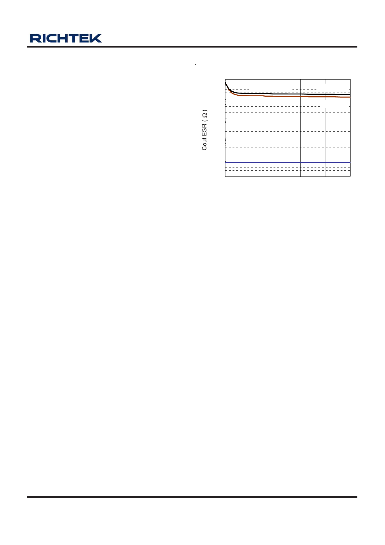
types due to the wide stable ESR range. Figure 1 shows
the curves of allowable ESR range as a function of load
current for various output voltages and capacitor values.
Output capacitor of larger capacitance can reduce noise
and improve load-transient response, stability, and PSRR.
The output capacitor should be located not more than
0.5" from the VOUT pin of the RT9168/A and returned to a
clean analog ground.
Note that some ceramic dielectrics exhibit large
capacitance and ESR variation with temperature. It may
be necessary to use 2.2μF or more to ensure stability at
temperatures below -10°C in this case. Also, tantalum
capacitors, 2.2μF or more may be needed to maintain
capacitance and ESR in the stable region for strict
application environment.
Region of Stable Cout ESR v.s Load Current
100
Unstable Region
COUT = 4.7uF
10
Stable Region
COUT = 1uF
1
0.1
0.01
Unstable Region
0.001
0
40
80
120
160
200
Load Current (mA)
Figure 1
Tantalum capacitors maybe suffer failure due to surge
current when it is connected to a low-impedance source
of power (like a battery or very large capacitor). If a
tantalum capacitor is used at the input, it must be
guaranteed to have a surge current rating sufficient for
the application by the manufacture.
Load-Transient Considerations
The RT9168/A load-transient response graphs (see Typical
Operating Characteristics) show two components of the
output response: a DC shift from the output impedance
due to the load current change, and the transient response.
The DC shift is quite small due to the excellent load
regulation of the IC. Typical output voltage transient spike
for a step change in the load current from 0mA to 50mA is
tens mV, depending on the ESR of the output capacitor.
Increasing the output capacitor's value and decreasing the
ESR attenuates the overshoot.
Shutdown Input Operation
The RT9168/A is shutdown by pulling the EN input low,
and turned on by driving the input high. If this feature is
not to be used, the EN input should be tied to VIN to
keep the regulator on at all times (the EN input must not
be left floating).
DS9168/A-15 March 2007
www.richtek.com
7
Share Link: 