RPM5500 Просмотр технического описания (PDF) - ROHM Semiconductor
Номер в каталоге
Компоненты Описание
Список матч
RPM5500 Datasheet PDF : 8 Pages
| |||
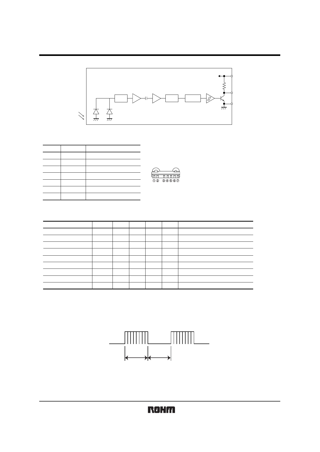
Photo Link Module
zBlock diagram
RPM5500 series
AMP
I/V
LIMITER
BPF
Comparator
Demodulator
and integrator
VCC
22k
ROUT
GND
zTerminal description
Pin No.
1
2
3
4
5
6
7
Pin name
VCC
GND
GND
GND
ROUT
GND
GND
Function
POWER SUPPLY
GROUND
GROUND
GROUND
OUTPUT TERMINAL
GROUND
GROUND
zElectrical, Optical characteristics (Unless otherwise noted, Ta = 25°C VCC=5V)
Parameter
Symbol Min. Typ. Max. Unit
Conditions
Consumption Current
ICC
−
0.95
1.5
mA No outside light, No signal input
Effective Distance
L
7
12
−
m Outer light condition Ee < 10 (Ix) ∗1
High Level Output Voltage
VH
4.5
−
−
V
∗1
Low Level Output Voltage
VL
−
−
0.5
V
Isink =< 200µA
∗1
ON Pulse Width
TON
400
600
800
µs Outer light condition Ee < 10 (Ix) ∗1
OFF Pulse Width
TOFF
400
600
800
µs Outer light condition Ee < 10 (Ix) ∗1
Center frequency
fo
−
∗3
−
kHz
Horizontal half angle
θ 1/2
−
42
−
deg
∗2
Vertical half angle
θ 1/2
−
38
−
deg
∗2
∗1 600/600µs burst wave is transmitted by standard transmitter. However, it must be measured after the initial transmission pulse is 10 pulse.
∗2 It is an angle when the linear arrival distance become half.
∗3 Three types of frequencies : 36.7, 37.9, 40kHz.
z Measurement Conditions
(1) Transmit signal
600µs
600µs
Carrier frequency=fo, Duty=50%
Fig.1 Transmit signal
2/7
Share Link: 