R3113D441X Просмотр технического описания (PDF) - RICOH Co.,Ltd.
Номер в каталоге
Компоненты Описание
Список матч
R3113D441X Datasheet PDF : 18 Pages
| |||
R3113D
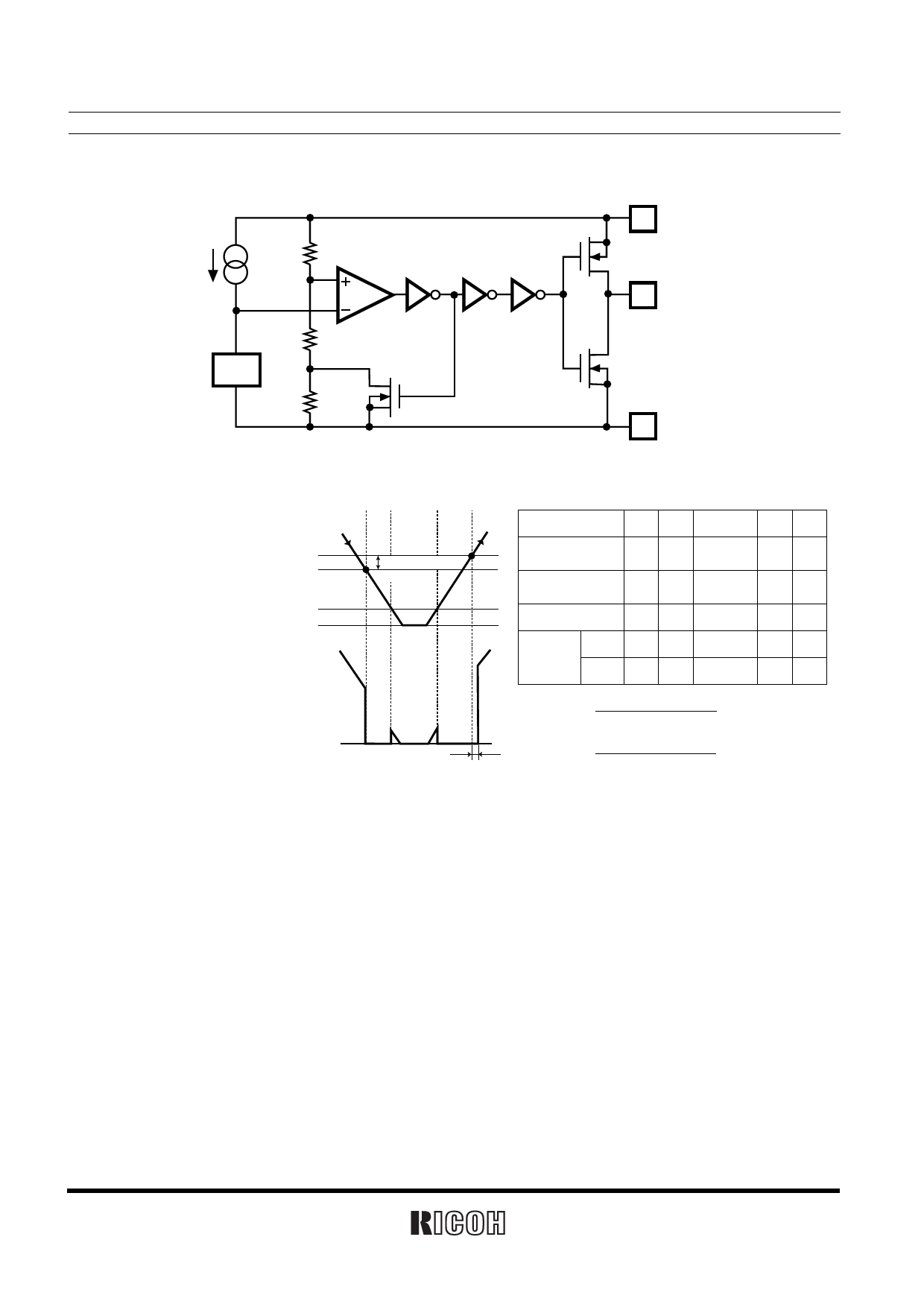
OPERATION
Ra
Rb
Vref
Rc
Comparator
Figure 1. Block Diagram
VDD
Pch
OUT
Nch
GND
Released Voltage(+VDET)
Supply Voltage Detector Threshold(-VDET)
(VDD)
Minimum Operating Voltage
GND
Output Voltage
(VOUT)
GND
12
3
45
B
Detector Threshold
Hysteresis
A
tPLH
Step
12
3
45
Comparator
Pin Input Voltage
I
Comparator
Output
H
II
III
IV V
L Inde-finite L H
Tr.1
OFF ON Inde-finite ON OFF
Output
Tr.
Pch ON OFF Inde-finite OFF ON
Nch OFF ON Inde-finite ON OFF
I.
Rb + Rc
Ra + Rb + Rc
× VDD
II.
Rb
Ra + Rb
× VDD
Figure 2. Operation Diagram
Step 1. The output voltage is equal to the supply voltage (VDD).
Step 2. At Point “A”, Vref >= VDD×(Rb+Rc)/(Ra+Rb+Rc) is true, as a result, the output of comparator is reverse,
and output voltage becomes to GND level. The voltage level of Point A means detector threshold voltage,
or (−VDET).
Step 3. When the supply voltage is less than minimum operating voltage, the operation of output transistor
becomes indefinite, and in the case that output is pulled up to VDD, the output voltage equals to VDD
voltage.
Step 4. The output voltage equals to GND level.
Step 5. At Point “B”, Vref >= VDD×Rb/(Ra+Rb) is true, Output of the comparator is reverse, and output voltage is
equal to the supply voltage, or (VDD). The voltage level of Point B means released voltage, or (+VDET).
∗ The difference between released voltage and detector threshold voltage is the detector threshold hysteresis.
10
Share Link: 