R1LV0408CSA-5SC Просмотр технического описания (PDF) - Renesas Electronics
Номер в каталоге
Компоненты Описание
Список матч
R1LV0408CSA-5SC Datasheet PDF : 14 Pages
| |||
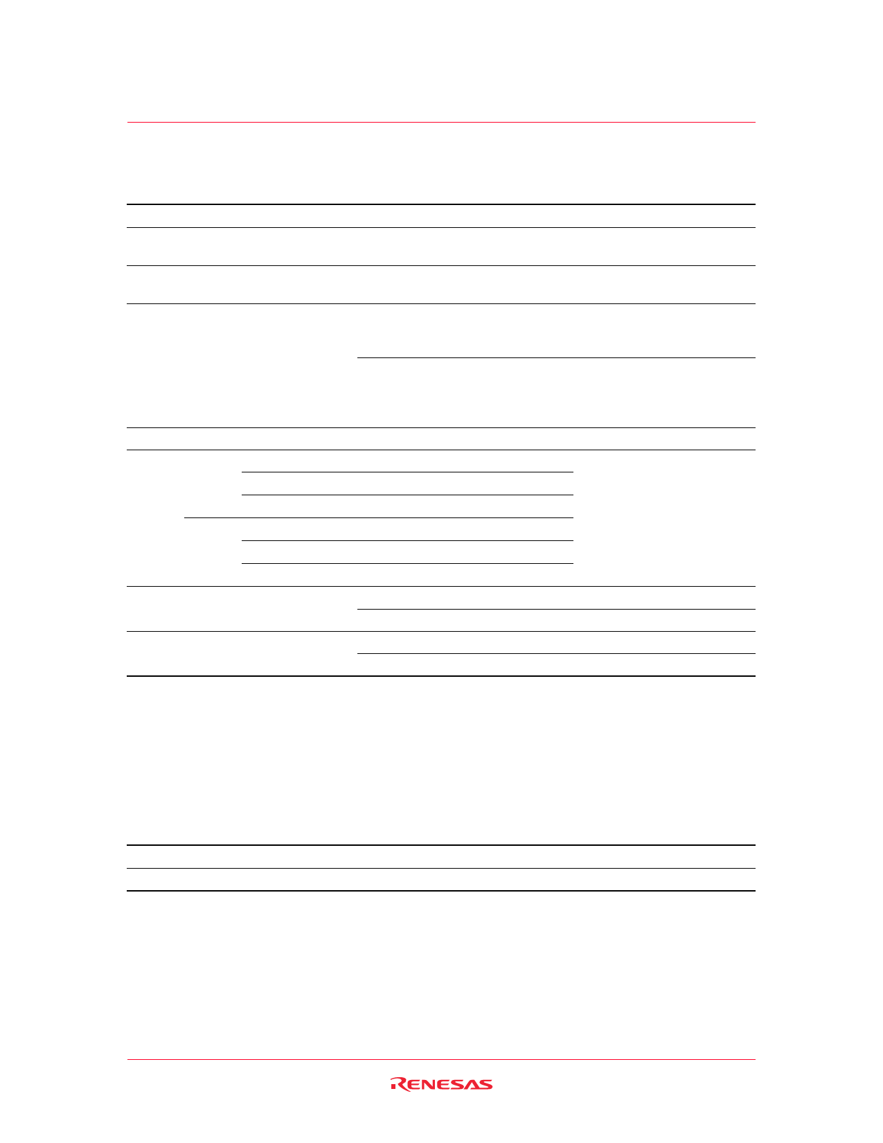
R1LV0408C-C Series
DC Characteristics
Parameter
Symbol Min Typ Max Unit Test conditions
Input leakage current
|ILI|
1 µA Vin = VSS to VCC
Output leakage current
Operating current
Average operating current
Standby current
|ILO|
ICC
ICC1
ICC2
ISB
1 µA CS# = VIH or OE# = VIH or
WE# = VIL or VI/O = VSS to VCC
5*1 10 mA CS# = VIL,
Others = VIH/ VIL, II/O = 0 mA
8*1 25 mA Min. cycle, duty = 100%,
CS# = VIL, Others = VIH/VIL
II/O = 0 mA
2*1 5 mA Cycle time = 1 µs,
duty = 100%,
II/O = 0 mA, CS# ≤ 0.2 V,
VIH ≥ VCC − 0.2 V, VIL ≤ 0.2 V
0.1*1 0.3 mA CS# = VIH
Standby −5SC
current
to +70°C
to +40°C
to +25°C
ISB1
ISB1
ISB1
8
0.7*2 3
0.5*1 3
µA Vin ≥ 0 V, CS# ≥ VCC − 0.2 V
µA
µA
−7LC
to +70°C
to +40°C
to +25°C
ISB1
ISB1
ISB1
16 µA
0.7*2 10 µA
0.5*1 10 µA
Output low voltage
VOL
0.4 V IOL = 2.1 mA
VOL2
0.2 V IOL = 100 µA
Output high voltage
VOH
2.4
V IOH = −1.0 mA
VOH2 VCC − 0.2 V IOH = −0.1 mA
Notes: 1. Typical values are at VCC = 3.0 V, Ta = +25°C and specified loading, and not guaranteed.
2. Typical values are at VCC = 3.0 V, Ta = +40°C and specified loading, and not guaranteed.
Capacitance
(Ta = +25°C, f = 1.0 MHz)
Parameter
Symbol Min Typ Max Unit Test conditions
Input capacitance
Cin
8
pF Vin = 0 V
Input/output capacitance
CI/O
10 pF VI/O = 0 V
Note: 1. This parameter is sampled and not 100% tested.
Note
1
1
Rev.2.00, May.25.2004, page 6 of 12
Share Link: 