PT7C4300 Просмотр технического описания (PDF) - Pericom Semiconductor
Номер в каталоге
Компоненты Описание
Список матч
PT7C4300 Datasheet PDF : 17 Pages
| |||
Data Sheet
PT7C4300
Real-time Clock Module (I2C Bus)
|||||||||||||||||||||||||||||||||||||||||||||||||||||||||||||||||||||||||||||||||||||||||||||||||||||||||||||||||||||||||||||||||||||||||||||||||||||||||||||||||||||||||||||||||||||||||||||||||||||||||||||||||||||||||||||||||||||||||||||||||||||||||||||||||||||||||||||||||||||||||||||||||||||||||||||||||||||||||||||||||||||||
2. Control and status register
Addr.
Description
D7
D6
D5
(hex)
07
Control
OUT
FT
S
(default)
0
0
1
a) OUT
• OUT: Set pin 7 output DC level..
OUT
Data
Read / Write
1 Set high level at pin 7.
0 Set low level at pin 7.
D4
D3
D2
D1
D0
Calibration
1
1
1
1
1
Description
Default
b) 512Hz output
• FT: 512Hz square wave output Enable bit, using for Frequency Test.
FT
Data
Description
Read / Write
0 Disable 512Hz output at pin 7.
1 Enable 512Hz output at pin 7.
Default
c) Calibration bits
• S: Sign bit.
S
Data
1
Read / Write
0
Indicate positive calibration.
Indicate negative calibration.
Description
Default
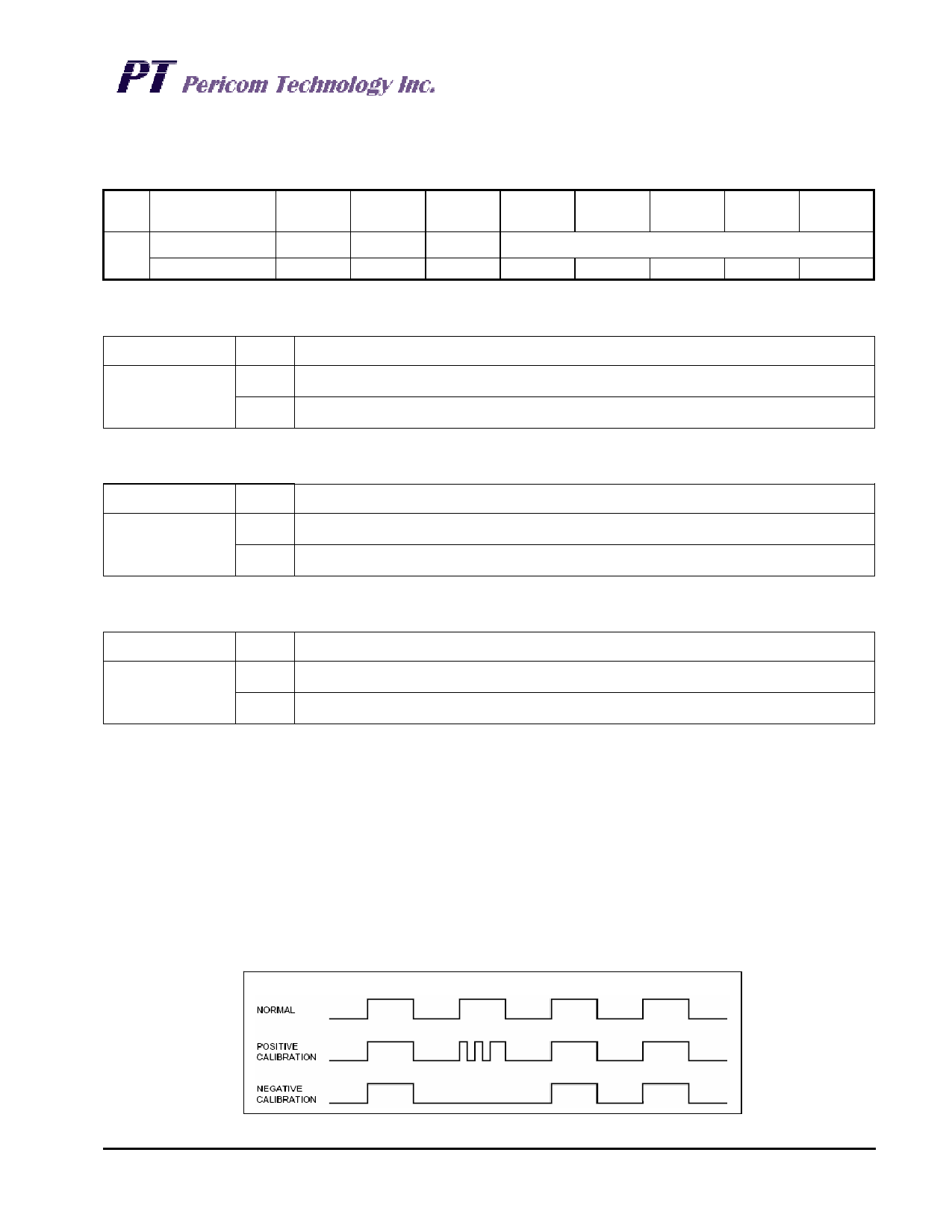
Calibration:
Calibration occurs within a 64minute cycle. The first 62 minutes in the cycle may, once per minute, have one second either
shortened by 128 or lengthened by 256 oscillator cycles. If a binary '1' is loaded into the register, only the first 2
minutes in the 64 minute cycle will be modified; if a binary 6 is loaded, the first 12 will be affected, and so on. Therefore, each
calibration step has the effect of adding 512 or subtracting 256 oscillator cycles for every 125,829,120 actual oscillator cycles, that
is +4.068 or –2.034 ppm of adjustment per calibration step in the calibration register. Assuming that the oscillator is in fact
running at exactly 32,768Hz, each of the 31 increments in the Calibration byte would represent +10.7 or –5.35 seconds per month
which corresponds to a total range of +5.5 or –2.75 minutes per month.
For example, a reading of 512.01024Hz would indicate a +20 ppm oscillator frequency error, requiring a –10 (XX001010) to be
loaded into the Calibration Byte for correction. Note that setting or changing the Calibration Byte does not affect the Frequency
test output frequency.
Clock calibration
PT0222(02/06)
6
Ver: 0
Share Link: 