PBL38570 Просмотр технического описания (PDF) - Ericsson
Номер в каталоге
Компоненты Описание
Список матч
PBL38570 Datasheet PDF : 12 Pages
| |||
PBL 385 70
Maximum Ratings
Parameter
Line voltage, tp = 2 s
Line current, continuous DIP
Line current, continuous SO package
Operating temperature range
Storage temperature range
No input should be set on higher level than pin 4 (+C).
MUTE
R = 0-4kΩ
L
0 ohm when artificial
VM
IM
line is used
5H+5H
Rfeed = 400Ω+400Ω
+
E = 48.5V
+
V2
ARTIFICIAL
LINE
C
600Ω
VL
IL
+ LINE MIC
IDC2
VDC2
IDC1
PBL 385 70
with external
components
See fig. 4
V1
VDC1
REC
V4
C = 1µF when artificial line is used
470µF when no artificial line
- LINE
Symbol
Min
VL
0
IL
0
IL
0
TAmb
-40
T
-55
Stg
Max
Unit
18
V
130
mA
100
mA
+70
°C
+125
°C
Z Mic = 350Ω
V3
ZRec= 350Ω
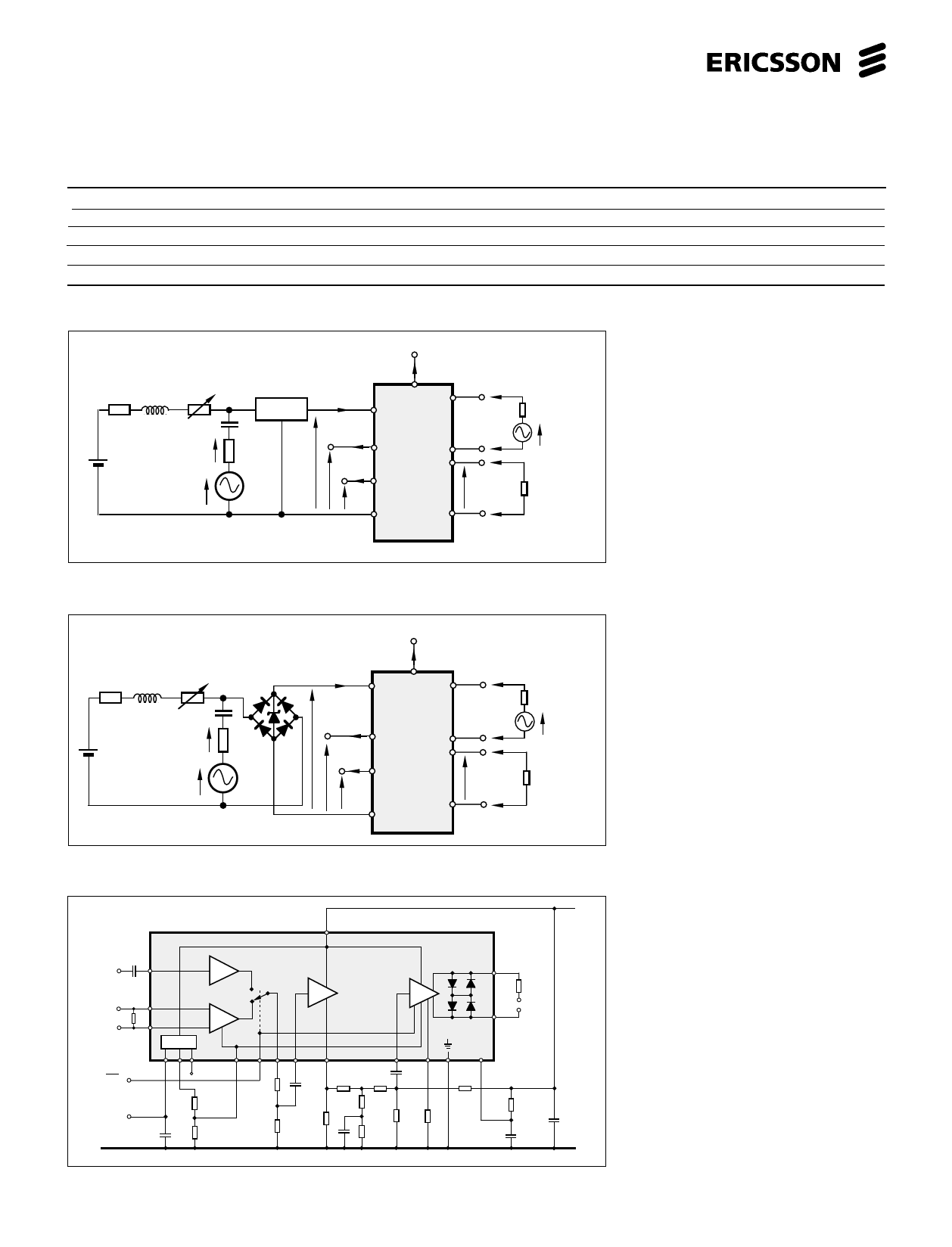
Figure 2. Test set up without rectifier
bridge.
MUTE
VM
IM
5H+5H RL = 0 - 4kΩ
Uz= 15-16V
IL
+ LINE
Rfeed = 400Ω+400Ω
+
E = 50.0V
+
1µF
V2
600Ω
V1
VL
MIC
IDC2
VDC2
IDC1
PBL 385 70
with external
components
See fig. 4
VDC1
REC
V4
- LINE
ZMic = 350Ω
V3
ZRec = 350Ω
Figure 3. Test set up with rectifier
bridge.
+Line
C9
220n
DTMF
10
input
AD
R16 12
Mic.
350Ω
2.7k
13
AM
DC-supply
89 7
6
Mute
(active low)
DC-output for
external devices
Sense input
R*1
Gain
regulation
+
C7
47µF
R*2
1
PBL 385 70
AT
AR
17
R14
310Ω
Rec.
18
350Ω
5 11 3
2
15
16
R4
R7
C3
910Ω
R10
6.2k
C6
47n
18k
100n
R8
560Ω
R6
R12
R13
R5
22k
75Ω
C5
11k
10Ω
R9
100n
11k
14
+4
R11
62k
R3
910Ω
C2
+
C1 47µF
15n
-Line
2
Figure 4. Circuit with external compon-
ents for test set up.
* Not used in test set up.
18 pin DIP package.
Share Link: 