PCD4440T Просмотр технического описания (PDF) - Philips Electronics
Номер в каталоге
Компоненты Описание
Список матч
PCD4440T Datasheet PDF : 20 Pages
| |||
Philips Semiconductors
Analog voice scrambler/descrambler
Product specification
PCD4440T
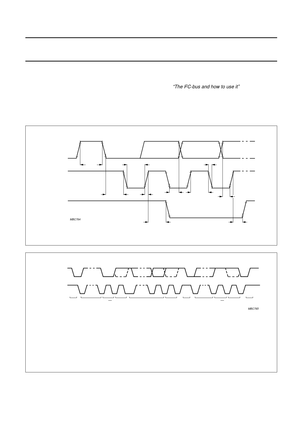
8.5 Timing specifications
The PCD4440T accepts data input from a microcontroller and operates as a ‘slave receiver’ via the I2C-bus. It supports
the ‘standard’ mode of the I2C-bus, but not the ‘fast’ mode detailed in “The I2C-bus and how to use it” document order
no. 9398 393 40011. The timing requirement are as follows:
Masters generate a bus clock with a maximum frequency of 100 kHz. Detailed timing is shown in Fig. 10, where the two
signal levels are LOW = VIL and HIGH = VIH, see Chapter 12. The time symbols are explained in Table 2. Figure 11
shows a complete data transfer.
handbook, full pagewidth
SDA
SCL
t BUF
SDA
MBC764
t LOW
tf
t HD;STA
tr
t HD;DAT
t HIGH
t SU;STA
Fig.10 Standard mode timing.
t SU;DAT
t SU;STO
handbook, full pageSwDidAth
SCL
1-7
8
9
START ADDRESS R/W ACK
CONDITION
1-7
8
9
1-7
8
9
DATA
ACK START ADDRESS R/W
CONDITION
ACK
STOP
MBC765
Clock LOW minimum = 4.7 µs; clock HIGH minimum = 4 µs.
The dashed line is the acknowledgment of the receiver.
Mark-to-space ratio = 1 : 1 (LOW-to-HIGH).
Maximum number of bytes is unrestricted.
Premature termination of transfer is allowed by generation of STOP condition.
Acknowledge clock bit must be provided by master.
Fig.11 Complete data transfer in standard mode.
1996 Dec 20
11
Share Link: 