MM74HC393(1999) Просмотр технического описания (PDF) - Fairchild Semiconductor
Номер в каталоге
Компоненты Описание
Список матч
MM74HC393 Datasheet PDF : 7 Pages
| |||
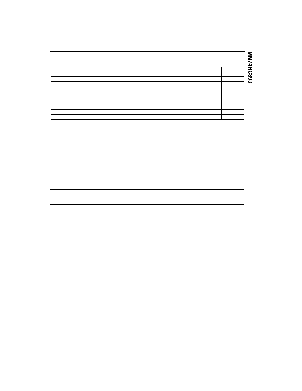
AC Electrical Characteristics
VCC = 5V, TA = 25°C, CL = 15 pF, tr = tf = 6 ns
Symbol
Parameter
fMAX
tPHL, tPLH
tPHL, tPLH
tPHL, tPLH
tPHL, tPLH
tPHL
tREM
tW
Maximum Operating Frequency
Maximum Propagation Delay, Clock A to QA
Maximum Propagation Delay, Clock A to QB
Maximum Propagation Delay, Clock A to QC
Maximum Propagation Delay, Clock A to QD
Maximum Propagation Delay, Clear to any Q
Minimum Removal Time
Minimum Pulse Width Clear or Clock
Conditions
Typ
Guaranteed
Limit
Units
50
30
MHz
13
20
ns
19
35
ns
23
42
ns
27
50
ns
15
28
ns
−2
5
ns
10
16
ns
AC Electrical Characteristics
CL = 50 pF, tr = tf = 6 ns (unless otherwise specified)
Symbol
Parameter
Conditions
VCC
TA = 25°C
TA = −40 to 85°C TA = −55 to 125°C Units
Typ
Guaranteed Limits
fMAX
Maximum Operating
Frequency
2.0V
4.5V
5
4
27
21
3
18
MHz
6.0V
31
24
20
MHz
tPHL, tPLH Maximum Propagation
Delay Clock A to QA
2.0V
45
120
150
4.5V
15
24
30
6.0V
13
21
26
180
ns
35
ns
31
ns
tPHL, tPLH Maximum Propagation
Delay Clock A to QB
2.0V
68
190
240
4.5V
23
38
47
6.0V
20
32
40
285
ns
57
ns
48
ns
tPHL, tPLH Maximum Propagation
Delay Clock A to QC
2.0V
90
240
300
4.5V
30
48
60
6.0V
26
41
51
360
ns
72
ns
61
ns
tPHL, tPLH Maximum Propagation Delay
Clock to QD
2.0V
100
290
360
4.5V
35
58
72
6.0V
30
50
62
430
ns
87
ns
75
ns
tPHL
Maximum Propagation
Delay Clear to any Q
2.0V
54
165
210
4.5V
18
33
41
250
ns
49
ns
6.0V
15
28
35
42
ns
tREM
Minimum Clear
Removal Time
2.0V
4.5V
25
25
5
5
25
ns
5
ns
6.0V
5
5
5
ns
tW
Minimum Pulse Width
Clear or Clock
2.0V
30
80
100
4.5V
10
16
20
120
ns
24
ns
6.0V
9
14
18
20
ns
tTHL, tTLH Maximum Output
Rise and Fall Time
2.0V
30
75
95
4.5V
8
15
19
110
ns
22
ns
6.0V
7
13
16
19
ns
tr, tf
Maximum Input
Rise and Fall Time
1000
500
1000
500
1000
ns
500
ns
400
400
400
ns
CPD
Power Dissipation
(per counter)
42
pF
Capacitance (Note 5)
CIN
Maximum Input Capacitance
5
10
10
10
pF
Note 5: CPD determines the no load dynamic power consumption, PD = CPD VCC2f + ICC VCC, and the no load dynamic current consumption,
IS = CPD VCCf + ICC.
3
www.fairchildsemi.com
Share Link: 