ML7012-04 Просмотр технического описания (PDF) - Oki Electric Industry
Номер в каталоге
Компоненты Описание
Список матч
ML7012-04 Datasheet PDF : 22 Pages
| |||
1Semiconductor
FEDL 7012-04-01
ML7012-04
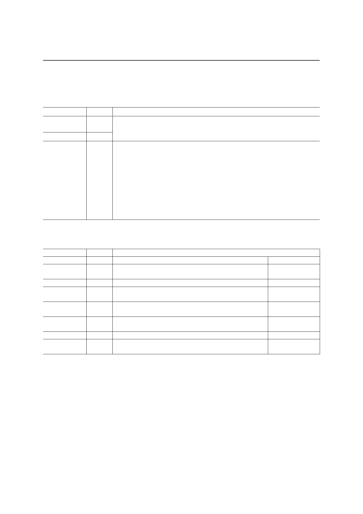
PIN DESCRIPTIONS
System & Clock
Symbol
OSCO
OSC1
PDN/RST
I/O
Description
I
Pins to connect crystal, resistors and capacitors for the master clock oscillation. When
supplying the master clock from an external source, use OSC0 and leave OSC1 open.
O Master clock frequency = 11.0592 MHz. When PDN/RST = “0”, OSC1 = “1”.
Power-down and reset control input pin. When PDN/RST = “0”, this device is in the
power-down state and internal circuits are reset.
“0”: Power-down state, “1”: Normal operation
After power-on, use this pin after setting it to “0” for 1 µs or more to reset internal
I
circuits. Waiting for 230 ms or more is required until restarting a normal operation after
reset release.
If this pin remains at “0” after power-on, the internal circuits become undefined and
the power-down current may increase. To avoid this, input “1” to this pin and start
oscillation or input the master clock to operate the internal circuits, and then set it to
“0”
V.24 Serial Interface
Symbol
STD
SRD
RTS
CTS
DCD
DSR
DTR
CI
I/O
Description
I Send data input pin
Receive data output pin
O When PDN/RST = “0”, SRD outputs “1”.
I RTS (Request to Send) signal input pin
CTS (Clear to Send) signal output pin
O When PDN/RST = “0”, CTS outputs “1”.
O
DCD (Data Carrier Detect) signal output pin
When PDN/RST = “0”, DCD outputs “1”.
O
DSR (Data Set Ready) signal output pin
When PDN/RST = “0”, DSR outputs “1”.
I DTR (Data Terminal Ready) signal input pin
O
CI (Calling Indicator) signal output pin (*2)
When PDN/RST = “0”, CI outputs “1”.
0: Space, 1: Mark
0: Space, 1: Mark
0: On, 1: Off
0: On, 1: Off
0: On, 1: Off
0: On, 1: Off
0: On, 1: Off
0: On, 1: Off
4/22
Share Link: 