MIC5212 Просмотр технического описания (PDF) - Micrel
Номер в каталоге
Компоненты Описание
Список матч
MIC5212 Datasheet PDF : 9 Pages
| |||
MIC5212
Applications Information
Input Capacitor
A 1µF capacitor should be placed from IN to GND if there is
more than 10 inches of wire between the input and the AC
filter capacitor or if a battery is used as the input.
Output Capacitor
An output capacitor is required between OUT and GND to
prevent oscillation. 1.0µF minimum is recommended. Larger
values improve the regulator’s transient response. The out-
put capacitor value may be increased without limit.
The output capacitor should have an ESR (Effective Series
Resistance) of about 5Ω or less and a resonant frequency
above 1MHz. Ultra-low-ESR capacitors may cause a low-
amplitude oscillation and/or underdamped transient response.
Most tantalum or aluminum electrolytic capacitors are ad-
equate; film types will work, but are more expensive. Since
many aluminum electrolytic capacitors have electrolytes that
freeze at about –30°C, solid tantalum capacitors are recom-
mended for operation below –25°C.
At lower values of output current, less output capacitance is
required for output stability. The capacitor can be reduced to
0.47µF for current below 10mA or 0.33µF for currents below
1mA.
No-Load Stability
The MIC5212 will remain stable and in regulation with no load
(other than the internal voltage divider) unlike many other
voltage regulators. This is especially important in CMOS
RAM keep-alive applications.
Dual-Supply Operation
When used in dual supply systems where the regulator load
is returned to a negative supply, the output voltage must be
diode clamped to ground.
Power SO-8 Thermal Characteristics
One of the secrets of the MIC5212’s performance is its power
SO-8 package featuring half the thermal resistance of a
standard SO-8 package. Lower thermal resistance means
more output current or higher input voltage for a given
package size.
Micrel
Lower thermal resistance is achieved by joining the four
ground leads with the die attach paddle to create a single-
piece electrical and thermal conductor. This concept has
been used by MOSFET manufacturers for years, proving
very reliable and cost effective for the user.
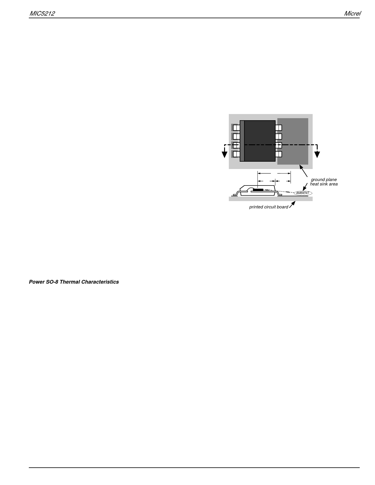
Thermal resistance consists of two main elements, θJC
(junction-to-case thermal resistance) and θCA (case-to-ambi-
ent thermal resistance). See Figure 1. θJC is the resistance
from the die to the leads of the package. θCA is the resistance
from the leads to the ambient air and it includes θCS (case-to-
sink thermal resistance) and θSA (sink-to-ambient thermal
resistance).
SO-8
θJA
θJC
θCA
ground plane
heat sink area
AMBIENT
printed circuit board
Figure 1. Thermal Resistance
Using the power SO-8 reduces the θJC dramatically and
allows the user to reduce θCA. The total thermal resistance,
θJA (junction-to-ambient thermal resistance) is the limiting
factor in calculating the maximum power dissipation capabil-
ity of the device. Typically, the power SO-8 has a θJC of
20°C/W, this is significantly lower than the standard SO-8
which is typically 75°C/W. θCA is reduced because pins 5
through 8 can now be soldered directly to a ground plane
which significantly reduces the case-to-sink thermal resis-
tance and sink to ambient thermal resistance.
April 2003
7
MIC5212
Share Link: 