MC33215 Просмотр технического описания (PDF) - Motorola => Freescale
Номер в каталоге
Компоненты Описание
Список матч
MC33215 Datasheet PDF : 20 Pages
| |||
Freescale SMeCm3i3c2o15nductor, Inc.
from Pin REG by the internal circuit (the 10 µA term in the
formulas). This built–in feature drops the line voltage and
therefore enables parallel operation.
The voltage over the line driver has to be limited to 12 V to
protect the device. A zener of 11 V at VLN is therefore the
maximum advised.
VDD Supply
The internal circuitry for the line driver and handset
interface is powered via VDD. This pin may also be used to
power peripherals like a dialer or microcontroller. The voltage
at VDD is not internally regulated and is a direct result of the
line voltage setting and the current consumption at VDD
+ ǒ ) Ǔ internally (IVDD) and externally (IPER). It follows that:
VDD VLN – IVDD IPER x Rset
For correct operation, it must be ensured that VDD is
biased at 1.8 V higher than SLP. This translates to a
maximum allowable voltage drop across ZVDD of
Vzener – 1.8 V. In the typical application, this results in a
maximum allowable current consumption by the peripherals
of 2.0 mA.
VMC Supply
At VMC, a stabilized voltage of 1.75 V is available for
powering the handset microphone. Due to this stabilized
supply, microphones with a low supply rejection can be used
which reduces system costs. In order to support the parallel
operation of the telephone set, the voltage at VMC will be
maintained even at very low line currents down to 4.0 mA.
Under normal supply conditions of line currents of 20 mA
and above, the supply VMC is able to deliver a guaranteed
minimum of 1.0 mA. However, for lower line currents, the
supply capability of VMC will decrease.
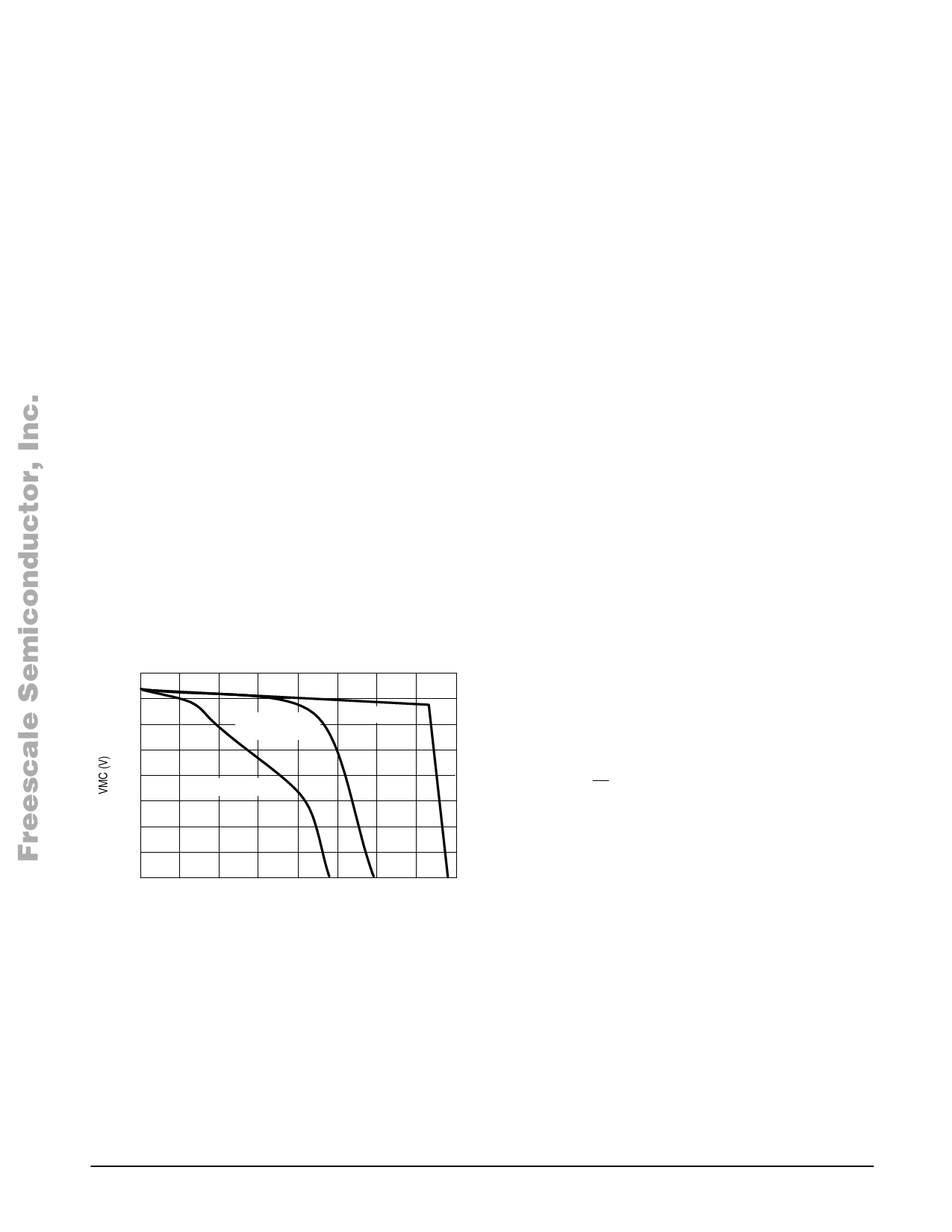
Figure 5. VMC Under Different Microphone Loads
1.8
1.7
1.6
Iline = 4.0 mA
Iline = 20 mA
2.7 k VMC–VHF
1.5
1.4
Iline = 4.0 mA
1.3
1.2
1.1
1.0
0 0.2 0.4 0.6 0.8 1.0 1.2 1.4 1.6
IVMC (mA)
If, during parallel operation, a high current is required from
VMC, a 2.7 k resistor between VMC and VHF can be applied.
In Figure 5, the VMC voltage under different microphone
currents, is shown.
VHF Supply
VHF is a stabilized supply which powers the internal
duplex controller part of the MC33215, and which is also
meant to power the base microphone or other peripherals.
The base microphone however, can also be connected to
VMC, which is preferred in case of microphones with a poor
supply rejection. Another possibility is to create an additional
filter at VHF, like is shown in the typical application. The
supply capability of VHF is guaranteed as 2.0 mA for line
currents of 20 mA and greater.
Since in parallel operation not enough line current is
available to power a loudspeaker and thus having a
speakerphone working, the current internally supplied to VHF
is cut around 10 mA of line current to save current for the
handset operated part. A small hysteresis is built in to avoid
system oscillations.
When the current to VHF is cut, the voltage at VHF will
drop rapidly due to the internal consumption of 1.4 mA and
the consumption of the peripherals. When VHF drops below
2.0 V, the device internally switches to the handset mode,
neglecting the state of the speakerphone select Pin SPS.
In case an application contains a battery pack or if it is
mains supplied, speakerphone operation becomes possible
under all line current conditions. In order to avoid switch–over
to handset operation below the 10 mA, VHF has to be
supplied by this additional power source and preferably kept
above 2.4 V.
VCC Supply
At VCC the major part of the line current is available for
powering the loudspeaker amplifier and peripheral circuitry.
This supply pin should be looked at as a current source since
the voltage on VCC is not stabilized and depends on the
instantaneous line voltage and the current to and consumed
from VCC.
The maximum portion of the line current which is available
+ ǒ ǒ ǓǓ at VCC is given by the following relation:
IVCC
10
11
x
Iline – IVDD
– IVMC – IVHF
This formula is valid when the voltage drop from VLN to
VCC is sufficient for the current splitter to conduct all this
current to VCC. When the drop is not sufficient, the current
source saturates and the surplus of current is conducted to
the power ground PGD to avoid distortion in the line driver. In
fact, when no current is drawn from VCC, the voltage at VCC
will increase until the current splitter is in balance. In Figure 6
this behavior is depicted.
MOTOROLA ANALOG IC DEVICEFDoArTAMore Information On This Product,
9
Go to: www.freescale.com
Share Link: 