MC33215 Просмотр технического описания (PDF) - Motorola => Freescale
Номер в каталоге
Компоненты Описание
Список матч
MC33215 Datasheet PDF : 20 Pages
| |||
Freescale SMeCm3i3c2o15nductor, Inc.
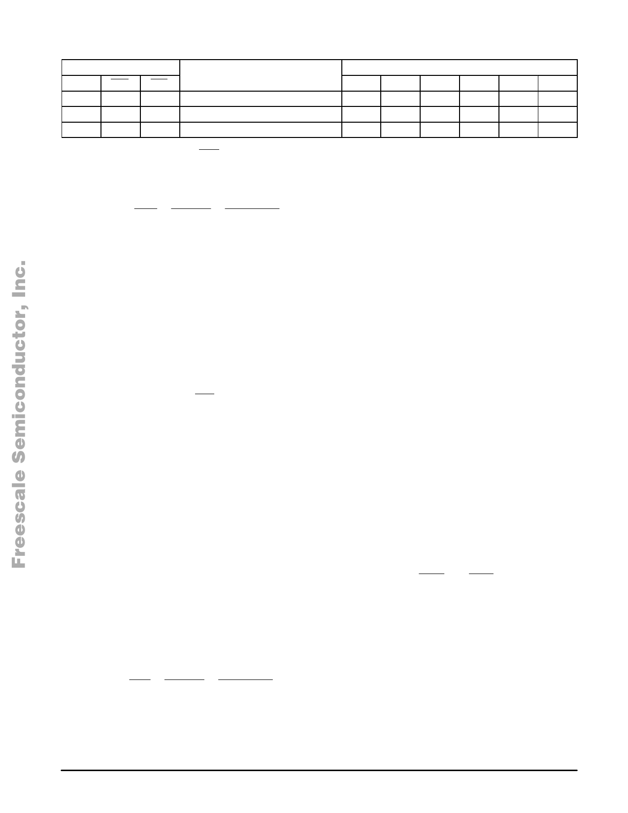
Table 2. Logic Table for Handsfree Mode
Logic Inputs
Amplifiers
SPS
ÁÁÁÁÁÁÁÁÁÁÁÁÁÁÁÁÁÁÁÁÁÁÁÁÁÁÁÁÁÁÁÁÁÁ 1
ÁÁÁÁÁÁÁÁÁÁÁÁÁÁÁÁÁÁÁÁÁÁÁÁÁÁÁÁÁÁÁÁÁÁ 1
ÁÁÁÁÁÁÁÁÁÁÁÁÁÁÁÁÁÁÁÁÁÁÁÁÁÁÁÁÁÁÁÁÁÁÁÁÁÁÁÁÁÁÁÁÁÁÁÁÁÁÁÁÁÁÁÁÁÁÁÁÁÁÁÁÁÁÁÁ 1
MUT
1
1
0
PRS
1
0
X
Mode
Handsfree Normal
Handsfree Privacy
Handsfree DTMF
HMIC BMIC DTMF
Rx
Off
On
Off
On
Off
Off
On
On
Off
Off
On
Off
RXatt
On
On
On
EAR
Off
Off
Off
By applying a logic 0 to Pin MUT, the DTMF mode is
entered where the DTMF amplifier is enabled and where the
Rx amplifier is muted. A DTMF signal can be sent to the line
via the MFI input for which the gain ADTMF is given as:
+ + ń ) ADTMF
Vline
VMFI
3.75
RSLP 11
x
Zline x
Zline
Zset
Zset
In the typical application, the gain equals 35 dB. The
DTMF gain can be controlled by a resistor divider at the input
MFI as shown in the typical application. The signal has to be
capacitively coupled to the input via CMFI which creates a
high pass filter with the input impedance. The line length
AGC has no effect on the DTMF gains.
The signal applied to the MFI input is made audible at the
earpiece output for confidence tone. The signal is internally
applied to the GRX pin where it is amplified via the EAR
amplifier which is used as a current to voltage amplifier. The
gain is therefore proportional to the feedback resistor RRXO.
For RRXO = 180 kΩ the gain equals 6.0 dB. The confidence
tone is also audible at the loudspeaker output when the
loudspeaker amplifier is activated, see speakerphone
operation.
By applying a logic 0 to Pin PRS, the MC33215 enters
privacy mode. In this mode, both handset and handsfree
microphone amplifiers are muted while the DTMF amplifier is
enabled. Through the MFI input, a signal, for example music
on hold, can be sent to the line. In the same way, the MFI
input can also be used to couple in signals from, for instance,
an answering machine.
HANDSFREE OPERATION
Handsfree operation, including DTMF and Privacy modes,
can be performed by making Pin SPS high according Table 2.
The handset amplifiers will be switched off while the base
amplifiers will be activated. The MC33215 performs all the
necessary functions, such as signal monitoring and
switch–over, under supervision of the duplex controller.
With the MC33215 also a group listening–in application
can be built. For more information on this subject please refer
to application note AN1574.
Base Microphone Amplifier
The base microphone can be capacitively connected to
the circuit via the differential input BM1 and BM2. The setup
is identical to the one for the handset microphone amplifier.
The total transmit voltage gain ABM from the base
microphone inputs to the line is:
+ + ń ) ABM
Vline
VBM
37.5
RSLP 11
x
Zline x
Zline
Zset
Zset
With the typical application and Zline = 600 Ω the transmit
gain calculates as 55 dB.
The electret base microphone can be supplied directly
from VHF but it is advised to use an additional RC filter to
obtain a stable supply point, as shown in the typical
application. The microphone can also be supplied by VMC.
The transmit gain is set by adjusting the sensitivity of the
base microphone by adjusting the resistors RBM1 and RBM2.
It is not advised to adjust the gain by including series
resistors towards the Pins BM1 and BM2.
A high pass filter is introduced by the coupling capacitors
CBM1 and CBM2 in combination with the input impedance. A
low pass filter can be created by putting capacitors in parallel
with the resistors RBM1 and RBM2.
Loudspeaker Amplifier
The loudspeaker amplifier of the MC33215 has three major
benefits over most of the existing speakerphone loudspeaker
amplifiers: it can be supplied and used in a telephone line
powered application but also stand alone, it has an all NPN
bootstrap output stage which provides maximum output
swing under any supply condition, and it includes a
peak–to–peak limiter to limit the distortion at the output.
The loudspeaker amplifier is powered at Pin VLS. In
telephone line powered applications, this pin should be
connected to VCC where most of the line current is available,
see the VCC supply paragraph. In an application where an
external power supply is used, VLS and thus the loudspeaker
amplifier can be powered separately from the rest of the
circuit. The amplifier is grounded to PGD, which is the circuits
power ground shared by both the loudspeaker amplifier and
the current splitter of the VCC supply. Half the supply voltage
of VLS is at BVO, filtered with a capacitor to VLS. This
voltage is used as the reference for the output amplifier.
The receive signal present at RLS can be capacitively
coupled to LSI via the resistor RLSI. The overall gain from
RLS to LSO follows as:
+ + ALS
VLSO
VRLS
–
RLSF
RLSI
x
4.0
In the typical application this leads to a loudspeaker gain
ALS of 26 dB. The above formula follows from the fact that the
overall amplifier architecture from RLS to LSO can be looked
at as an inverting voltage amplifier with an internal current
gain from LSI to LSF of 4. The input LSI is a signal current
summing node which allows other signals to be applied here.
12
For More Information On This ProdMuOcTtO, ROLA ANALOG IC DEVICE DATA
Go to: www.freescale.com
Share Link: 