MC33288 Просмотр технического описания (PDF) - Motorola => Freescale
Номер в каталоге
Компоненты Описание
Список матч
MC33288 Datasheet PDF : 8 Pages
| |||
Freescale Semiconductor, Inc.
MC33288
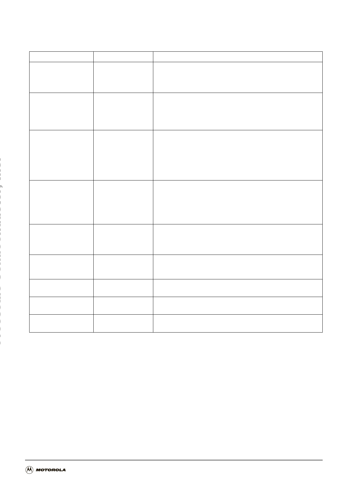
PINS FUNCTION DESCRIPTION
Pin No.
TAB
6,7,8
13,14,15
3
18
19
20
2
4, 9, 10, 11, 12, 17
5, 16
11
Name/Function
Vbat
Supply Voltage
OUT1
OUTPUT Channel 1
OUT 2
OUTPUT Channel 2
IN 1
INPUT Channel 1
IN 2
INPUT Channel 2
Status
Status for both
Channels
Wlp
Warning Lamp Output
Cur R
Load Current Sense
NC
Not Connected
DNC
Do Not Connect
GND
GROUND
Description
The backside TAB is connected to the power supply of the
MC33288DH. In addition to its supply function, this pin contributes to
the thermal behaviour of the device by conducting the heat from the
switching MOSFET to the printed circuit board.
Pins 6,7,8 are the source of the output1 25mOhm MOSFET1. Pins
13,14,15 are source of the output 2 25mOhm MOSFET2. They deliver
current to the connected loads and are respectively controlled via the
IN1 and IN2 pins. These outputs are current limited and thermally
protected.
These are the device input pins which directly control their associated
outputs. The levels are CMOS compatible. When the input is a logic
low, the associated output MOSFET is in the off state. When input is
high, the MOSFET is turned on and the load is activated.
When both inputs are low, the device is in standby mode and its
supply current is reduced. Each input pin has an internal active pull
down, so that it will not float if disconnected.
The Fault output is an open drain indication that goes active low when
a fault mode (Openload, Overtemp) is detected by the device on
either one channel or both simultaneously. Its internal structure is an
open drain architecture with an internal clamp at 6V. An external pull
up resistor connected to Vdd (5V) is needed. See Functional Truth
Table.
This pin is the source of a 3.2 Ohm MOSFET. This output is current
limited and thermally protected. It delivers current through the
connected load when both IN1 and IN2 inputs are logic high. It is usually
used as a warning lamp driver for Flasher application.
The Current Sense pin deliver a ratioed amount (1/1000) of the sum
of the currents that can be used to generate signal ground referenced
output voltages for use by the microcontroller.
These pins are not used.
These pins must not be connected.
This is the Ground pin of the device.
SolidFSotarteMRoerleayIfnofroArmutoamtiootniveOFnlaTshheisr APprpoldicuactito,ns
2
Go to: www.freescale.com
Share Link: 