MB3782 Просмотр технического описания (PDF) - Fujitsu
Номер в каталоге
Компоненты Описание
Список матч
MB3782 Datasheet PDF : 27 Pages
| |||
MB3782
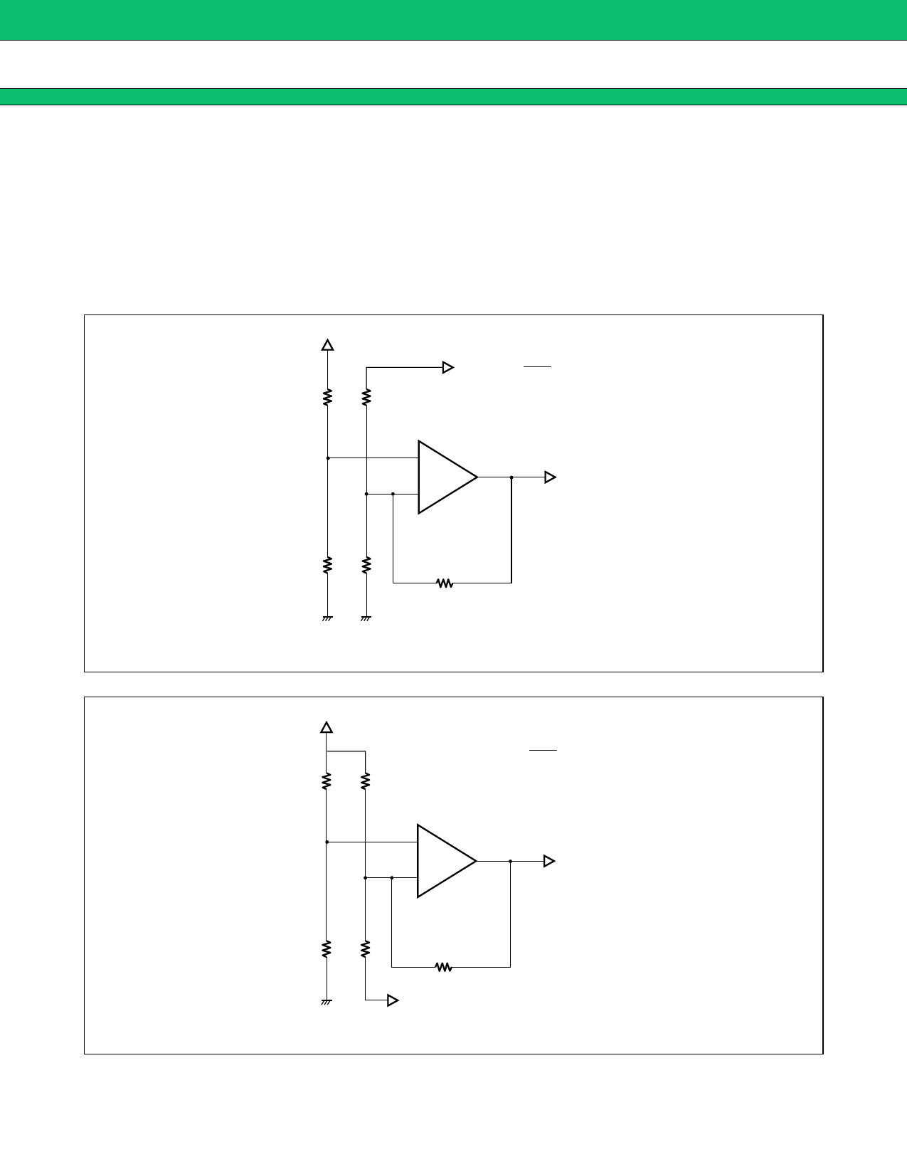
s SETTING OUTPUT VOLTAGE
The following diagrams show the connections used to set the output voltage.
Because the power supply to the error amps is provided by the same reference voltage circuit used for the other
internal circuits, the common-mode input voltage range is set at 1.05 V to 1.45 V.
The reference voltage input to the +IN and -IN pins should be set at 1.25 V (VREF/2). The method of connection
for channel 1 is different from channel 2 and channel 3. In addition, channel 1 is capable of picking up both
positive and negative voltages, while channel 2 and channel 3 can pick up only positive output voltages.
VREF
R
V0 +
V0 + =
VREF
· (R1 + R2)
2·R2
R1
+
–
pin 6
R
R2
RNF
Figure 2 Error amp (channel 1) connection: Output voltage VO positive
VREF
R
R1
+
–
V0 – = –
VREF
· (R1 + R2) + VREF
2·R2
pin 6
R
R2
RNF
V0 –
Figure 3 Error amp (channel 1) connection: Output voltage VO positive
7
Share Link: 