MAX4670 Просмотр технического описания (PDF) - Maxim Integrated
Номер в каталоге
Компоненты Описание
Список матч
MAX4670 Datasheet PDF : 20 Pages
| |||
Integrated T1/E1/J1 Short-Haul and
Long-Haul Protection Switch
MAX4670
NO1
NC1
NO2
NC2
0.6Ω
NO3
0.6Ω
NC3
0.6Ω
NO4
0.6Ω
NC4
0.6Ω
NO5
0.6Ω
NC5
0.6Ω
NO6
0.6Ω
NC6
NO7
NC7
NO8
NC8
V+
RX
RX
TX
TX
TX
TX
RX
RX
COM1
COM2
INA
COM3
COM4
INB
COM5
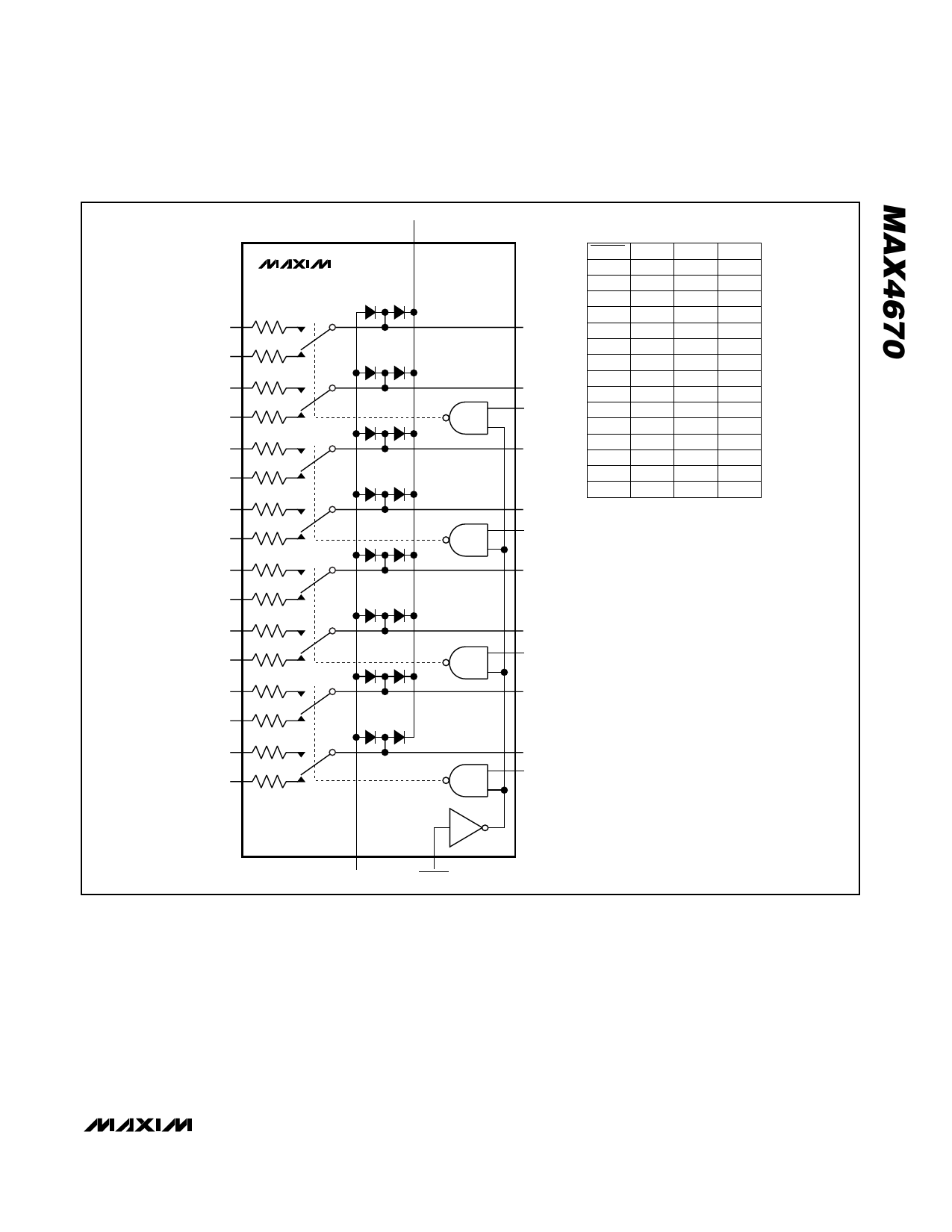
SWITCH INA NC1/NC2 NO1/NO2
LOW
X
OFF
ON
HIGH LOW OFF
ON
HIGH HIGH
ON
OFF
INB NC3/NC4 NO3/NO4
LOW
X
OFF
ON
HIGH LOW OFF
ON
HIGH HIGH
ON
OFF
INC NC5/NC6 NO5/NO6
LOW
X
OFF
ON
HIGH LOW OFF
ON
HIGH HIGH
ON
OFF
IND NC7/NC8 NO7/NO8
LOW
X
OFF
ON
HIGH LOW OFF
ON
HIGH HIGH
ON
OFF
COM6
INC
COM7
COM8
IND
Figure 1. Functional Diagram
GND
SWITCH
In a switching-card architecture, a common switching
card contains all the protection switches for the T1/E1/J1
lines entering the system (see Figures 7 and 8).
With an adjacent card architecture, the switches pro-
tecting any given line card reside physically in the adja-
cent line card (see Figures 9 and 10).
Receive and transmit interfaces reside in the same
board for each T1/E1/J1 port. The diagrams represent
the typical interface transformers and resistors recom-
mended for Dallas/Maxim LIUs, such as the DS21Q55.
The protection switches are placed in the low-voltage
side of the transformer to meet the isolation require-
ments. Note that there is also a TVS in the line side of
the transformers. The receive and transmit resistors pro-
vide impedance matching to the T1/E1/J1 transmission
cable characteristic impedance. Refer to Application
Note 2857 for more information on T1/E1/J1 applications.
_______________________________________________________________________________________ 9
Share Link: 