MAX1771 Просмотр технического описания (PDF) - Maxim Integrated
Номер в каталоге
Компоненты Описание
Список матч
MAX1771 Datasheet PDF : 16 Pages
| |||
12V or Adjustable, High-Efficiency,
Low IQ, Step-Up DC-DC Controller
The control circuitry allows the IC to operate in continu-
ous-conduction mode (CCM) while maintaining high
efficiency with heavy loads. When the power switch is
turned on, it stays on until either 1) the maximum on-
time one-shot turns it off (typically 16µs later), or 2) the
switch current reaches the peak current limit set by the
current-sense resistor.
The MAX1771 switching frequency is variable (depend-
ing on load current and input voltage), causing variable
switching noise. However, the subharmonic noise gen-
erated does not exceed the peak current limit times the
filter capacitor equivalent series resistance (ESR). For
example, when generating a 12V output at 500mA from
a 5V input, only 100mV of output ripple occurs using
the circuit of Figure 2a.
Low-Voltage Start-Up Oscillator
The MAX1771 features a low input voltage start-up oscil-
lator that guarantees start-up with no load down to 2V
when operating in bootstrapped mode and using inter-
nal feedback resistors. At these low voltages, the supply
voltage is not large enough for proper error-comparator
operation and internal biasing. The start-up oscillator
has a fixed 50% duty cycle and the MAX1771 disre-
gards the error-comparator output when the supply volt-
age is less than 2.5V. Above 2.5V, the error-comparator
and normal one-shot timing circuitry are used. The low-
voltage start-up circuitry is disabled if non-bootstrapped
mode is selected (FB is not tied to ground).
Shutdown Mode
When SHDN is high, the MAX1771 enters shutdown
mode. In this mode, the internal biasing circuitry is
turned off (including the reference) and VOUT falls to a
diode drop below VIN (due to the DC path from the
input to the output). In shutdown mode, the supply
current drops to less than 5µA. SHDN is a TTL/CMOS
logic-level input. Connect SHDN to GND for normal
operation.
__________________Design Procedure
Setting the Output Voltage
To set the output voltage, first determine the mode of
operation, either bootstrapped or non-bootstrapped.
Bootstrapped mode provides more output current
capability, while non-bootstrapped mode reduces the
supply current (see Typical Operating Characteristics).
If a decaying voltage source (such as a battery) is
used, see the additional notes in the Low Input Voltage
Operation section.
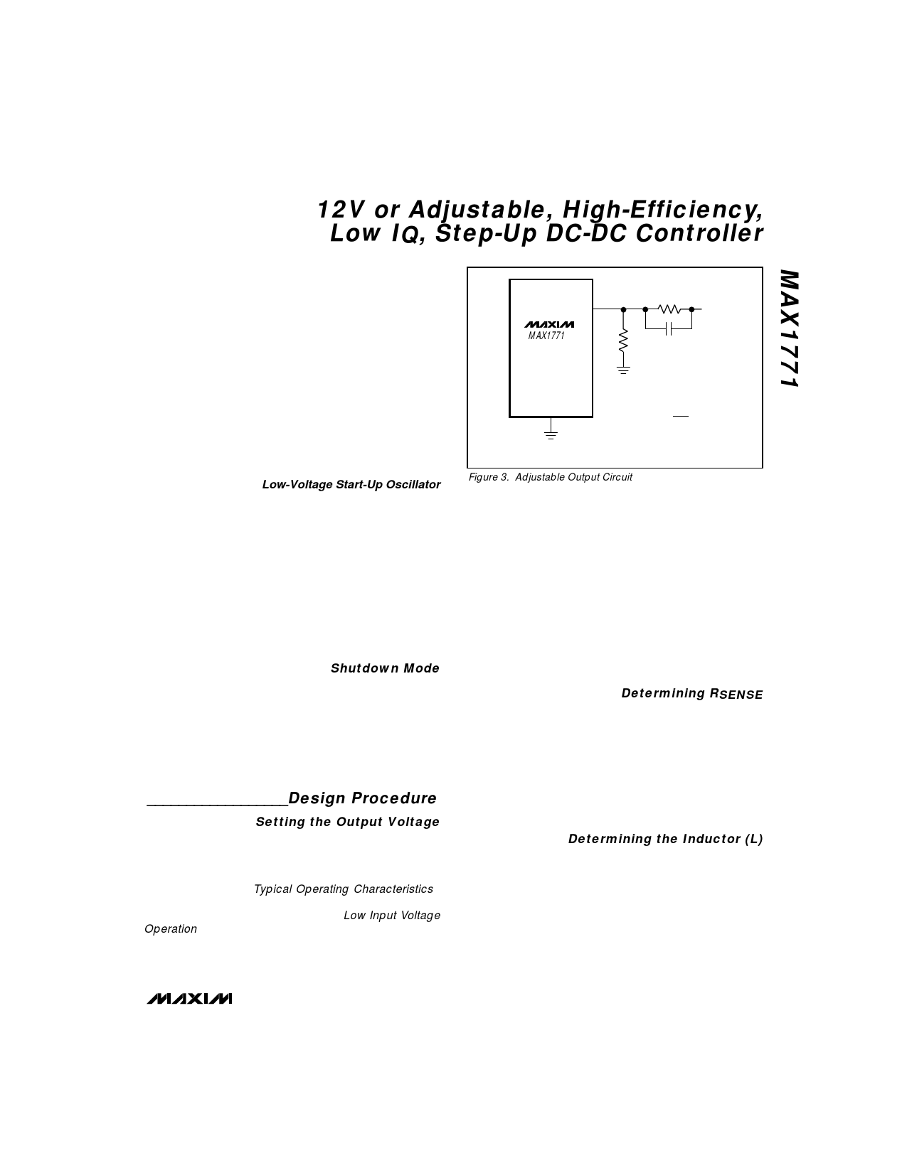
The MAX1771’s output voltage can be adjusted from
very high voltages down to 3V, using external resistors
FB
MAX1771
R2
VOUT
R1
C5*
R1 = 10k TO 500k
GND
( ) R2 = R1 VOUT -1
VREF
VREF = 1.5V
* SEE TEXT FOR VALUE
Figure 3. Adjustable Output Circuit
R1 and R2 configured as shown in Figure 3. For
adjustable-output operation, select feedback resistor
R1 in the 10kΩ to 500kΩ range. R2 is given by:
( ) R2 = (R1) –V–O–U––T -1
VREF
where VREF equals 1.5V.
For preset-output operation, tie FB to GND (this
forces bootstrapped-mode operation.
Figure 2 shows various circuit configurations for boot-
strapped/non-bootstrapped, preset/adjustable operation.
Determining RSENSE
Use the theoretical output current curves shown in
Figures 4a–4d to select RSENSE. They were derived
using the minimum (worst-case) current-limit compara-
tor threshold value over the extended temperature
range (-40°C to +85°C). No tolerance was included for
RSENSE. The voltage drop across the diode was
assumed to be 0.5V, and the drop across the power
switch rDS(ON) and coil resistance was assumed to be
0.3V.
Determining the Inductor (L)
Practical inductor values range from 10µH to 300µH.
22µH is a good choice for most applications. In appli-
cations with large input/output differentials, the IC’s
output current capability will be much less when the
inductance value is too low, because the IC will always
operate in discontinuous mode. If the inductor value
is too low, the current will ramp up to a high level before
the current-limit comparator can turn off the switch.
The minimum on-time for the switch (tON(min)) is
_______________________________________________________________________________________ 9
Share Link: 