MAX147ACAP(2001) Просмотр технического описания (PDF) - Maxim Integrated
Номер в каталоге
Компоненты Описание
Список матч
MAX147ACAP Datasheet PDF : 24 Pages
| |||
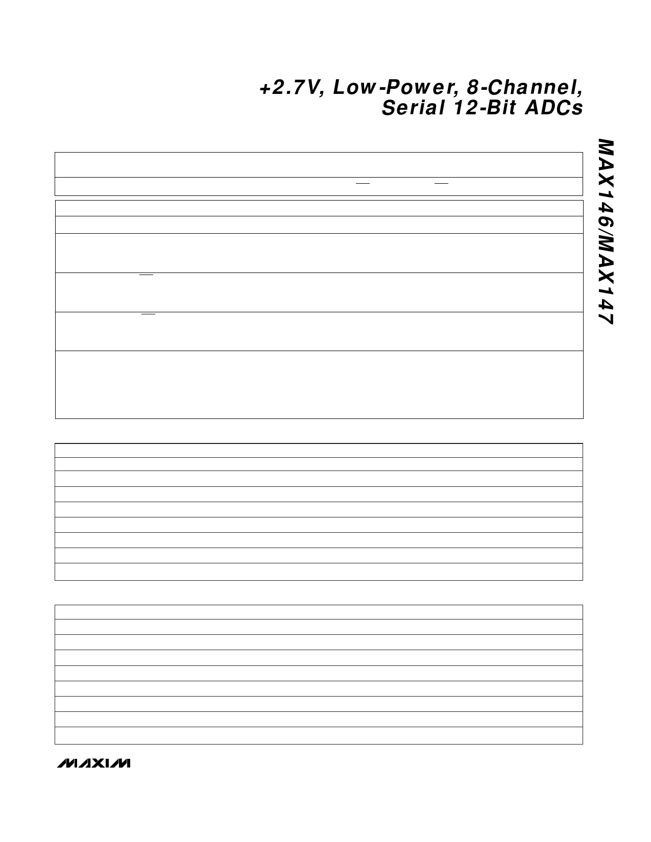
+2.7V, Low-Power, 8-Channel,
Serial 12-Bit ADCs
Table 1. Control-Byte Format
BIT 7
(MSB)
BIT 6
BIT 5
BIT 4
BIT 3
BIT 2
BIT 1
BIT 0
(LSB)
START
SEL2
SEL1
SEL0
UNI/BIP
SGL/DIF
PD1
PD0
BIT
7(MSB)
6
5
4
NAME
START
SEL2
SEL1
SEL0
DESCRIPTION
The first logic “1” bit after CS goes low defines the beginning of the control byte.
These three bits select which of the eight channels are used for the conversion (Tables 2 and 3).
3
UNI/BIP
1 = unipolar, 0 = bipolar. Selects unipolar or bipolar conversion mode. In unipolar mode, an
analog input signal from 0V to VREF can be converted; in bipolar mode, the signal can range
from -VREF/2 to +VREF/2.
2
SGL/DIF
1 = single ended, 0 = differential. Selects single-ended or differential conversions. In single-
ended mode, input signal voltages are referred to COM. In differential mode, the voltage
difference between two channels is measured (Tables 2 and 3).
1
PD1
0(LSB)
PD0
Selects clock and power-down modes.
PD1
PD0
Mode
0
0
Full power-down
0
1
Fast power-down (MAX146 only)
1
0
Internal clock mode
1
1
External clock mode
Table 2. Channel Selection in Single-Ended Mode (SGL/DIF = 1)
SEL2
0
1
SEL1
0
0
SEL0
0
0
CH0
+
CH1
+
CH2
CH3
CH4
CH5
0
0
1
+
1
0
1
+
0
1
0
1
1
0
+
+
0
1
1
1
1
1
Table 3. Channel Selection in Differential Mode (SGL/DIF = 0)
CH6
+
CH7
+
COM
–
–
–
–
–
–
–
–
SEL2
0
0
0
0
1
1
1
1
SEL1
0
0
1
1
0
0
1
1
SEL0
0
1
0
1
0
1
0
1
CH0
+
–
CH1
–
+
CH2
+
–
CH3
–
+
CH4
+
–
CH5
–
+
CH6
CH7
+
–
–
+
______________________________________________________________________________________ 11
Share Link: 