M54HC365D Просмотр технического описания (PDF) - STMicroelectronics
Номер в каталоге
Компоненты Описание
Список матч
M54HC365D Datasheet PDF : 11 Pages
| |||
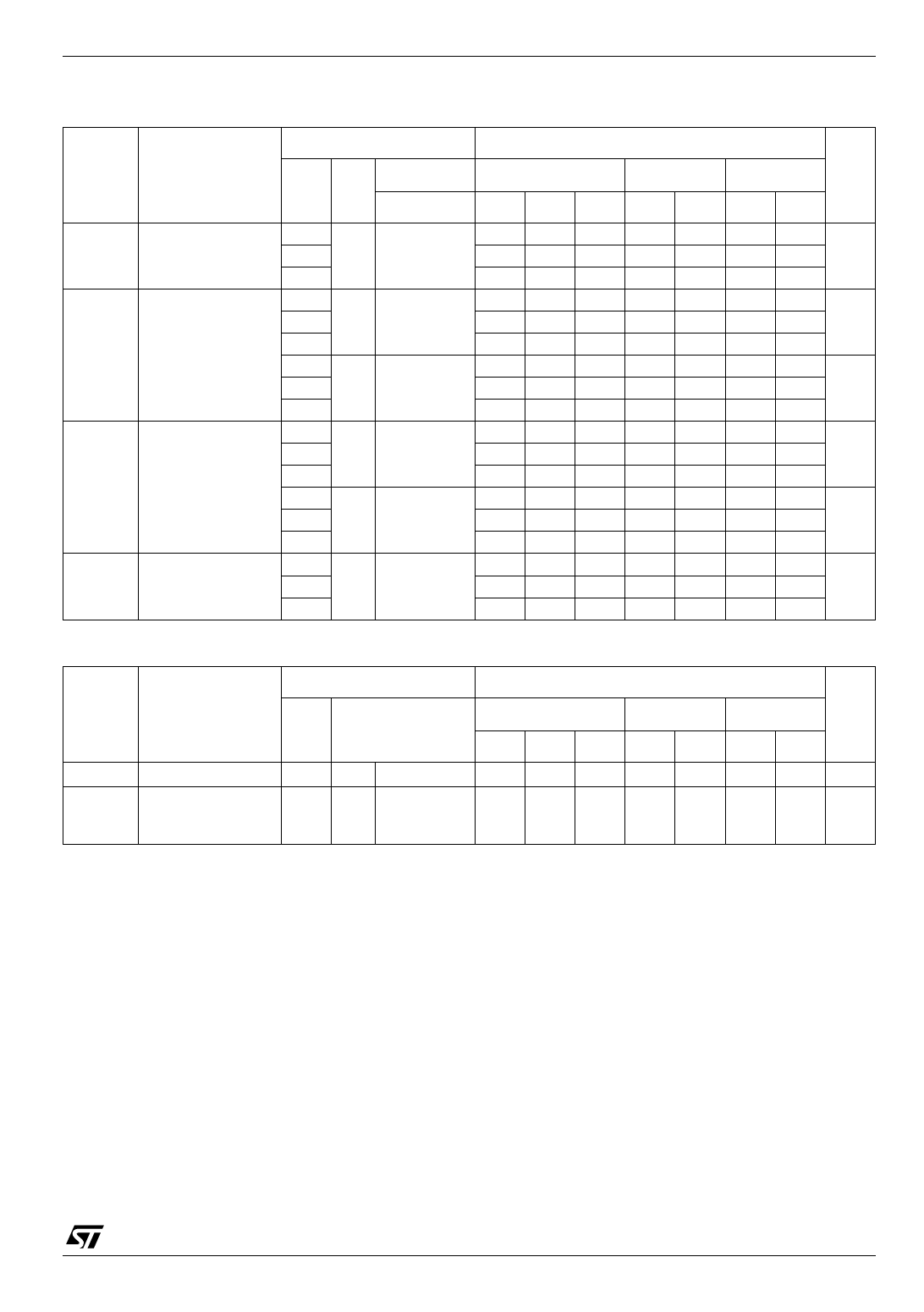
M54HC365
Table 6: AC Electrical Characteristics (CL = 50 pF, Input tr = tf = 6ns)
Test Condition
Symbol
Parameter
VCC CL
(V) (pF)
tTLH tTHL Output Transition
Time
tPLH tPHL Propagation Delay
Time
tPZL tPZH High Impedance
Output Enable
Time
tPLZ tPHZ High Impedance
Output Disable
Time
2.0
4.5 50
6.0
2.0
4.5 50
6.0
2.0
4.5 150
6.0
2.0
4.5 50 RL = 1 KΩ
6.0
2.0
4.5 150 RL = 1 KΩ
6.0
2.0
4.5 50 RL = 1 KΩ
6.0
Table 7: Capacitive Characteristics
Value
TA = 25°C
-40 to 85°C -55 to 125°C Unit
Min. Typ. Max. Min. Max. Min. Max.
25 60
75
90
7 12
19
18 ns
6 10
13
15
38 90
115
135
12 18
23
27 ns
10 15
20
23
51 130
165
195
17 26
33
39 ns
14 22
28
33
64 130
165
195
16 26
33
39 ns
14 22
28
33
76 150
190
225
19 30
38
45 ns
16 26
32
38
42 130
165
195
18 26
33
39 ns
15 22
28
33
Test Condition
Value
Symbol
Parameter
VCC
(V)
CIN Input Capacitance 5.0
CPD Power Dissipation
Capacitance (note 5.0
1)
TA = 25°C
-40 to 85°C -55 to 125°C Unit
Min. Typ. Max. Min. Max. Min. Max.
5 10
10
10 pF
27
pF
1) CPD is defined as the value of the IC’s internal equivalent capacitance which is calculated from the operating current consumption without
load. (Refer to Test Circuit). Average operating current can be obtained by the following equation. ICC(opr) = CPD x VCC x fIN + ICC/6 (per gate)
5/11
Share Link: 