LT3798EMSE Просмотр технического описания (PDF) - Linear Technology
Номер в каталоге
Компоненты Описание
Список матч
LT3798EMSE Datasheet PDF : 20 Pages
| |||
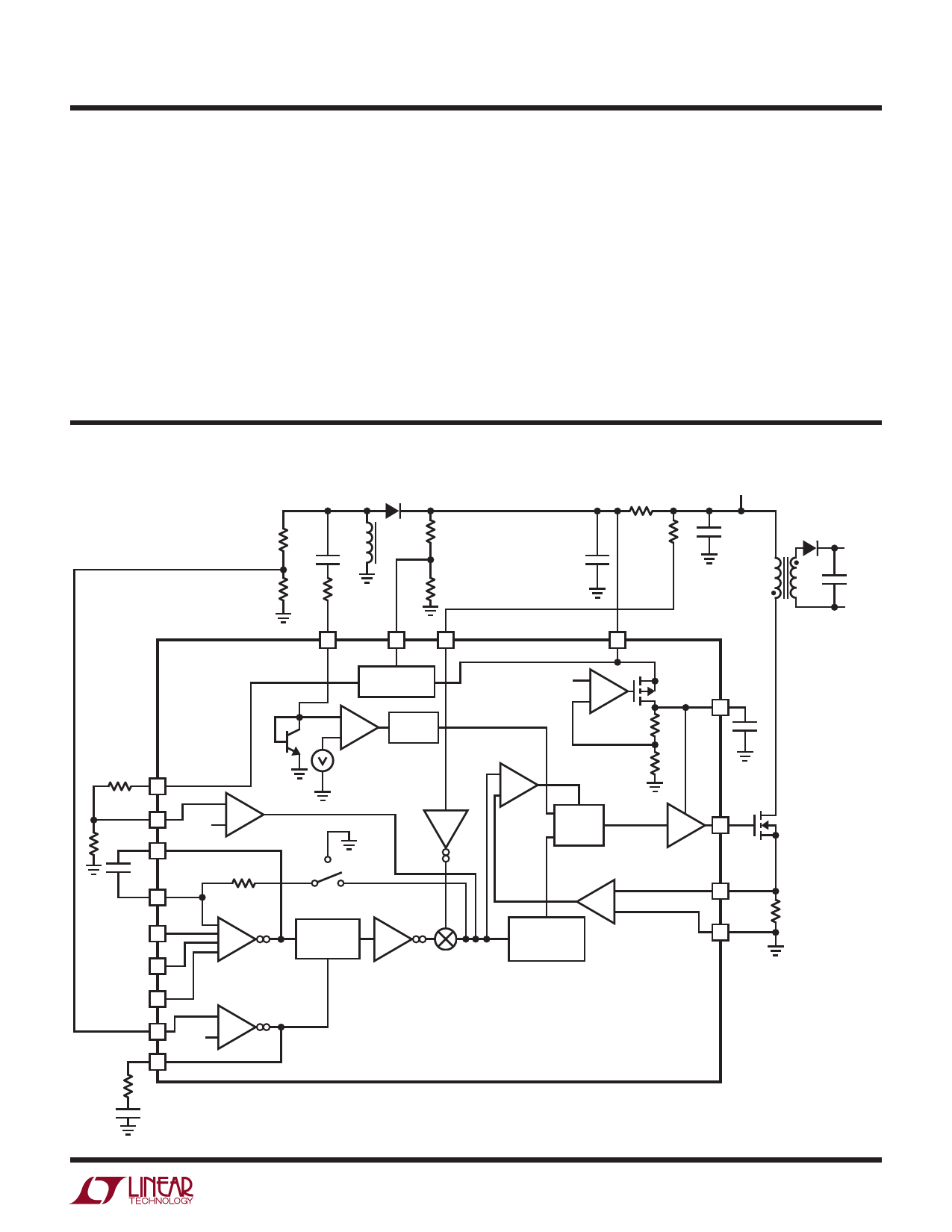
LT3798
PIN FUNCTIONS
GATE (Pin 14): N-Channel FET Gate Driver Output. Switches
between INTVCC and GND. Driven to GND during shutdown
state and stays high during low voltage states.
SENSE (Pin 15): The Current Sense Input for the Control
Loop. Kelvin connect this pin to the positive terminal of the
switch current sense resistor, RSENSE, in the source of the
NFET. The negative terminal of the current sense resistor
should be connected to the GND plane close to the IC.
VIN_SENSE (Pin 16): Line Voltage Sense Pin. The pin is
used for sensing the AC line voltage to perform power
factor correction. Connect a resistor in series with the
line voltage to this pin. If no PFC is needed, connect this
pin to INTVCC with a 25k resistor.
GND (Exposed Pad Pin 17): Ground. The exposed pad
of the package provides both electrical contact to ground
and good thermal contact to the printed circuit board.
The exposed pad must be soldered to the circuit board
for proper operation.
BLOCK DIAGRAM
D2
•
R13
R4
L1C
C1
R5
R15
R14
DCM
EN/UVLO VIN_SENSE
VRECTIFIED
R3
C3
VIN
R1
C2
D1
T1
VOUT +
L1A
L1B
C7
N:1
VOUT –
R8 VREF
OVP
R9 COMP+
C6
COMP–
S&H
A9
FB
R12
1M
CTRL1
–
CTRL2
+A5
CTRL3
FB
VC
1.22V
S&H
+
–A8
R10
C4
STARTUP
INTERNAL REG
+
+ –A2
600mV
–
ONE
SHOT
A3
1.22V –
+A7
CURRENT
COMPARATOR
+
–A1
SR
Q
S
MASTER
LATCH
SW1
A4
MINIMUM
A6
MULTIPLIER
LOW OUTPUT
CURRENT
OSCILLATOR
INTVCC
R7
C5
R11
GATE
DRIVER
SENSE
GND
R6
3798 BD
3798fa
7
Share Link: 