LT3782EUFD Просмотр технического описания (PDF) - Linear Technology
Номер в каталоге
Компоненты Описание
Список матч
LT3782EUFD Datasheet PDF : 20 Pages
| |||
LT3782
APPLICATIONS INFORMATION
From a known power dissipated in the power MOSFET, its
junction temperature can be obtained using the following
formula:
TJ = TA + PFET • RTH(JA)
The RTH(JA) to be used in this equation normally includes
the RTH(JC) for the device plus the thermal resistance from
the case to the ambient temperature (RTH(CA)). This value
of TJ can then be compared to the original, assumed value
used in the iterative calculation process.
Input Capacitor Choice
The input capacitor must have high enough voltage and
ripple current ratings to handle the maximum input voltage
and RMS ripple current rating. The input ripple current in
a boost circuit is very small because the input current is
continuous. With 2-phase operation, the ripple cancellation
1.00
0.90
0.80
0.70
0.60
1-PHASE
0.50
0.40
2-PHASE
0.30
0.20
0.10
0
0
0.2 0.4 0.6 0.8 1.0
DUTY CYCLE
3782 F04
Inorm
=
VIN
L • fs
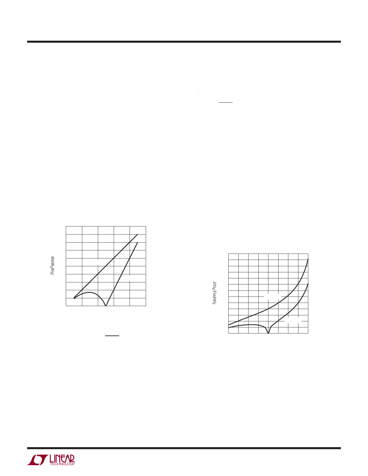
The RMS Ripple Current is About 29% of
the Peak-to-Peak Ripple Current.
Figure 5. Normalized Input Peak-to-Peak Ripple Current
will further reduce the input capacitor ripple current rating.
The ripple current is plotted in Figure 5. Please note that
the ripple current is normalized against
Inorm
=
VIN
L • fs
Output Capacitor Selection
The voltage rating of the output capacitor must be greater
than the maximum output voltage with sufficient derat-
ing. Because the ripple current in output capacitor is a
pulsating square wave in a boost circuit, it is important
that the ripple current rating of the output capacitor be
high enough to deal with this large ripple current. Figure
6 shows the output ripple current in the 1- and 2-phase
designs. As we can see, the output ripple current of a
2-phase boost circuit reaches almost zero when the duty
cycle equals 50% or the output voltage is twice as much as
the input voltage. Thus the 2-phase technique significantly
reduces the output capacitor size.
3.25
3.00
2.75
2.50
2.25
2.00
1.75
1.50
1.25
1.00
0.75
0.50
0.25
0
0.1
1-PHASE
2-PHASE
0.2 0.3 0.4 0.5 0.6 0.7 0.8 0.9
DUTY CYCLE OR (1-VIN/VOUT)
3782 F05
Figure 6. Normalized Output RMS Ripple Currents in Boost
Converter: 1-Phase and 2-Phase. IOUT Is the DC Output Current.
3782fg
13
Share Link: 