3575FE Просмотр технического описания (PDF) - Linear Technology
Номер в каталоге
Компоненты Описание
Список матч
3575FE Datasheet PDF : 24 Pages
| |||
LT3575
APPLICATIONS INFORMATION
Table 2. Common Resistor Values for 2:1 Transformers
VOUT (V)
NPS
RFB (kΩ) RREF (kΩ) RTC (kΩ)
3.3
2.00
37.4
6.04
18.7
5
2.00
56
6.04
28
12
2.00
130
6.04
66.5
15
2.00
162
6.04
80.6
Table 3. Common Resistor Values for 3:1 Transformers
VOUT (V)
NPS
RFB (kΩ) RREF (kΩ) RTC (kΩ)
3.3
3.00
56.2
6.04
20
5
3.00
80.6
6.04
28.7
10
3.00
165
6.04
54.9
Table 4. Common Resistor Values for 4:1 Transformers
VOUT (V)
NPS
RFB (kΩ) RREF (kΩ) RTC (kΩ)
3.3
4.00
76.8
6.04
19.1
5
4.00
113
6.04
28
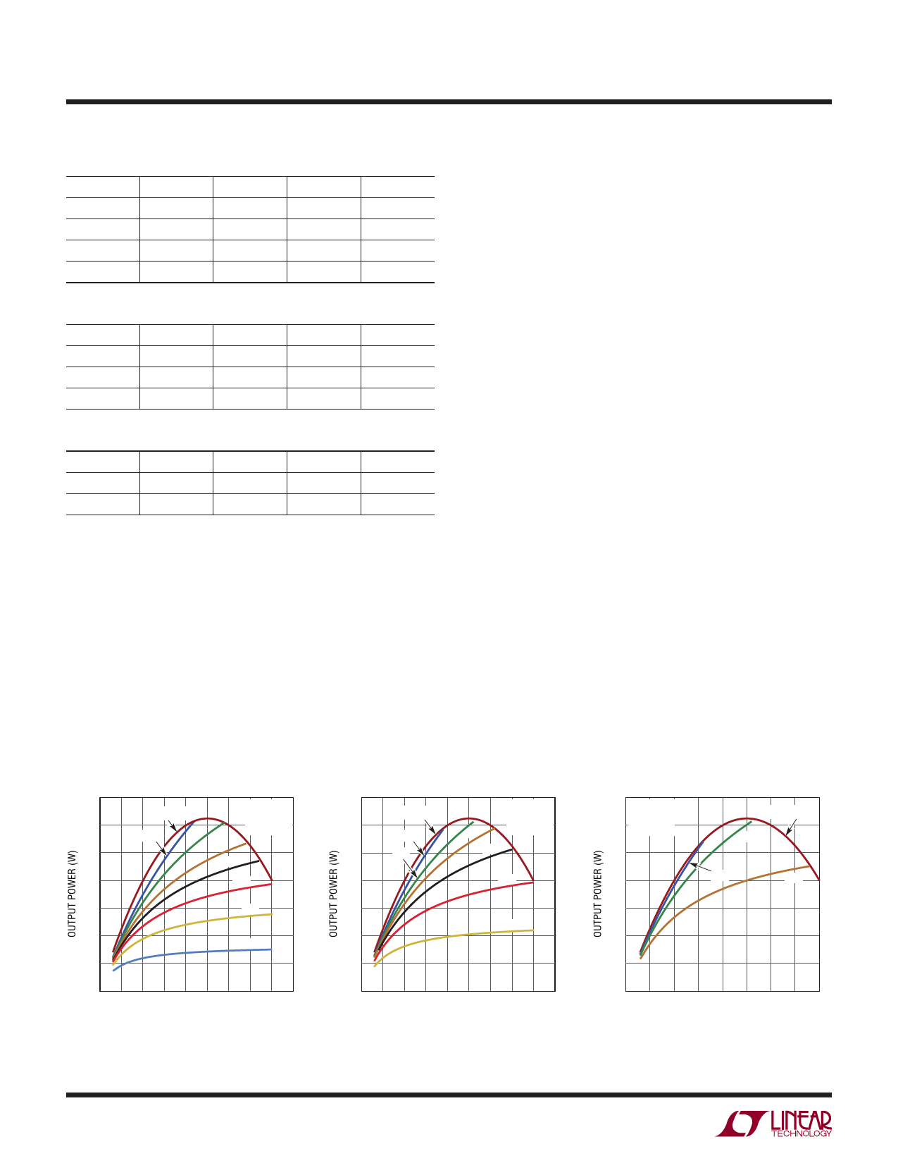
predict output power. In addition, the winding ratio can
be changed to multiply the output current at the expense
of a higher switch voltage.
The graphs in Figures 1-3 show the maximum output
power possible for the output voltages 3.3V, 5V, and 12V.
The maximum power output curve is the calculated output
power if the switch voltage is 50V during the off-time. To
achieve this power level at a given input, a winding ratio
value must be calculated to stress the switch to 50V,
resulting in some odd ratio values. The curves below are
examples of common winding ratio values and the amount
of output power at given input voltages.
One design example would be a 5V output converter with
a minimum input voltage of 20V and a maximum input
voltage of 30V. A three-to-one winding ratio fits this design
example perfectly and outputs close to ten watts at 30V
but lowers to eight watts at 20V.
Output Power
A flyback converter has a complicated relationship between
the input and output current compared to a buck or a
boost. A boost has a relatively constant maximum input
current regardless of input voltage and a buck has a
relatively constant maximum output current regardless of
input voltage. This is due to the continuous nonswitching
behavior of the two currents. A flyback converter has both
discontinuous input and output currents which makes it
similar to a nonisolated buck-boost. The duty cycle will
affect the input and output currents, making it hard to
TRANSFORMER DESIGN CONSIDERATIONS
Transformer specification and design is perhaps the most
critical part of successfully applying the LT3575. In addition
to the usual list of caveats dealing with high frequency
isolated power supply transformer design, the following
information should be carefully considered.
Linear Technology has worked with several leading magnetic
component manufacturers to produce pre-designed flyback
transformers for use with the LT3575. Table 5 shows the
details of several of these transformers.
14
MAX POUT
MAXIMUM
OUTPUT
12
10:1
7:1
POWER
10
5:1
4:1
8
3:1
6
2:1
4
1:1
2
0
0 5 10 15 20 25 30 35 40 45
INPUT VOLTAGE (V)
3575 F01
14
MAX POUT
MAXIMUM
OUTPUT
12
7:1
4:1
POWER
10
5:1
3:1
8
2:1
6
1:1
4
2
0
0 5 10 15 20 25 30 35 40 45
INPUT VOLTAGE (V)
3573 F02
14
MAXIMUM
OUTPUT
12 POWER
10
8
MAX POUT
2:1
3:1
1:1
6
4
2
0
0 5 10 15 20 25 30 35 40
INPUT VOLTAGE (V)
3573 F03
Figure 1. Output Power for 3.3V Output
Figure 2. Output Power for 5V Output
Figure 3. Output Power for 12V Output
3575f
10
Share Link: 