LT3573EMSE Просмотр технического описания (PDF) - Linear Technology
Номер в каталоге
Компоненты Описание
Список матч
LT3573EMSE Datasheet PDF : 26 Pages
| |||
LT3573
APPLICATIONS INFORMATION
Secondary Leakage Inductance
In addition to the previously described effects of leakage
inductance in general, leakage inductance on the second-
ary in particular exhibits an additional phenomenon. It
forms an inductive divider on the transformer secondary
that effectively reduces the size of the primary-referred
flyback pulse used for feedback. This will increase the
output voltage target by a similar percentage. Note that
unlike leakage spike behavior, this phenomenon is load
independent. To the extent that the secondary leakage
inductance is a constant percentage of mutual inductance
(over manufacturing variations), this can be accommodated
by adjusting the RFB/RREF resistor ratio.
Winding Resistance Effects
Resistance in either the primary or secondary will reduce
overall efficiency (POUT/PIN). Good output voltage regula-
tion will be maintained independent of winding resistance
due to the boundary mode operation of the LT3573.
Bifilar Winding
A bifilar, or similar winding technique, is a good way to
minimize troublesome leakage inductances. However, re-
member that this will also increase primary-to-secondary
capacitance and limit the primary-to-secondary breakdown
voltage, so, bifilar winding is not always practical. The
Linear Technology applications group is available and
extremely qualified to assist in the selection and/or design
of the transformer.
Setting the Current Limit Resistor
The maximum current limit can be set by placing a resistor
between the RILIM pin and ground. This provides some
flexibility in picking standard off-the-shelf transformers that
may be rated for less current than the LT3573’s internal
power switch current limit. If the maximum current limit
is needed, use a 10k resistor. For lower current limits,
the following equation sets the approximate current limit:
RILIM = 65 •103(1.6A −ILIM )+ 10k
The Switch Current Limit vs RILIM plot in the Typical Per-
formance Characteristics section depicts a more accurate
current limit.
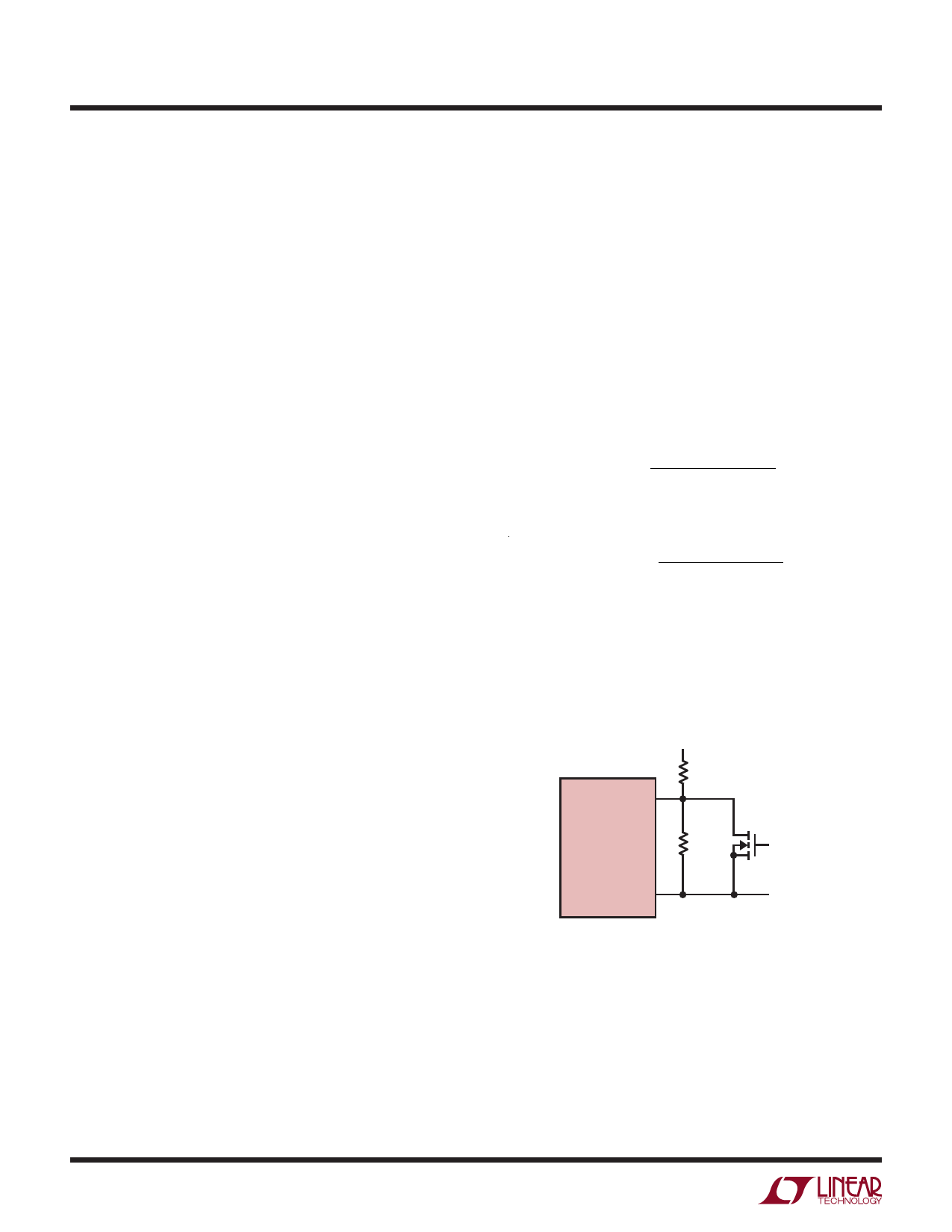
Undervoltage Lockout (UVLO)
The SHDN/UVLO pin is connected to a resistive voltage
divider connected to VIN as shown in Figure 8. The voltage
threshold on the SHDN/UVLO pin for VIN rising is 1.22V.
To introduce hysteresis, the LT3573 draws 2.5µA from the
SHDN/UVLO pin when the pin is below 1.22V. The hysteresis
is therefore user-adjustable and depends on the value of
R1. The UVLO threshold for VIN rising is:
VIN(UVLO,RISING)
=
1.22V
•(R1+
R2
R2)
+
2.5µA
•
R1
The UVLO threshold for VIN falling is:
VIN(UVLO,FALLING)
=
1.22V
•(R1+
R2
R2)
To implement external run/stop control, connect a small
NMOS to the UVLO pin, as shown in Figure 8. Turning the
NMOS on grounds the UVLO pin and prevents the LT3573
from operating, and the part will draw less than a 1µA of
quiescent current.
SHDN/UVLO
VIN
R1
RUN/STOP
LT3573
R2
CONTROL
(OPTIONAL)
GND
3573 F08
Figure 8. Undervoltage Lockout (UVLO)
14
For more information www.linear.com/LT3573
3573fd
Share Link: 