CDP152 Просмотр технического описания (PDF) - STMicroelectronics
Номер в каталоге
Компоненты Описание
Список матч
CDP152 Datasheet PDF : 11 Pages
| |||
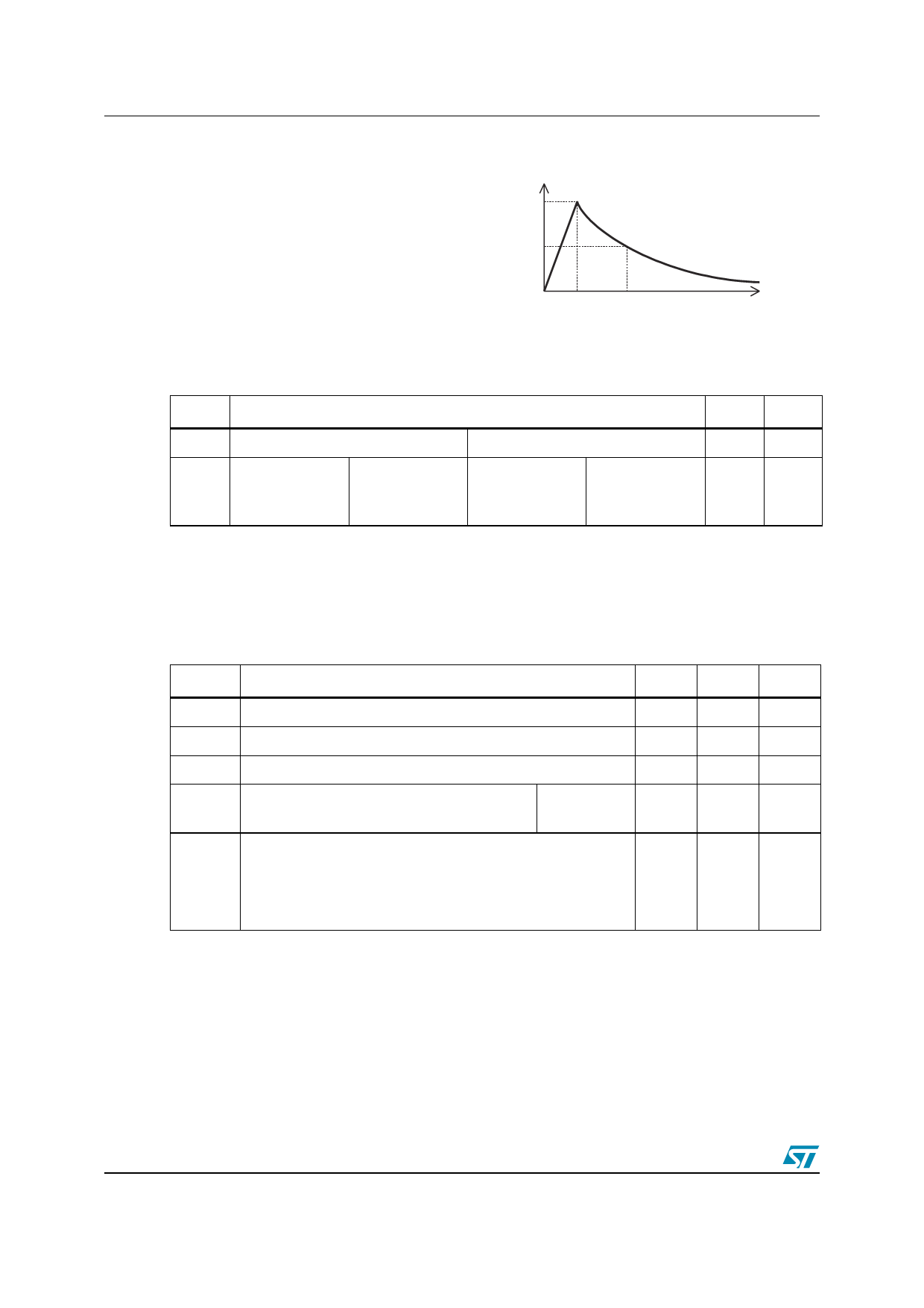
2 Characteristics
Figure 1. Repetitive peak pulse current
tr: rise time (µs)
tp: pulse duration (µs)
ex: Pulse waveform 10/1000 µs
tr = 10µs tp = 1000 µs
% IPP
100
50
0
tr
tp
LCDP1521
t
2.4 Parameters related to the diode line / GND (Tamb = 25°C)
Symbol
VF
VFP
(Note 1)
Test conditions
IF = 1 A
10/700 µs
1.2/50 µs
2/10 µs
1.5 kV
1.5 kV
2.5 kV
t = 500 µs
RS = 110 Ω
RS = 60 Ω
RS = 245 Ω
IPP = 10 A
IPP = 15 A
IPP = 10 A
Max Unit
2
V
5
10
V
20
Note: 1 See test circuit for VFP; RS is the protection resistor located on the line card.
2.5 Parameters related to the protection thyristor
(Tamb = 25°C unless otherwise specified)
Symbol
Test conditions
IGT
IH
VGT
IRG
VDGL
VGND / LINE = -48 V
VGATE = -48 V (Note 2)
at IGT
VRG = -150 V
VRG = -150 V
VGATE = -48 V (Note 3)
10/700 µs
1.2/50 µs
2/10 µs
1.5 kV
1.5 kV
2.5 kV
RS = 110 Ω
RS = 60 Ω
RS = 245 Ω
Tc=25°C
Tc=85°C
IPP = 10 A
IPP = 15 A
IPP = 10 A
Min
Max
Unit
0.1
5
mA
150
mA
2.5
V
5
50
µA
5
10
V
20
2 See functional holding current (IH) test circuit
3 See test circuit for VDGL. The oscillations with a time duration lower than 50ns are not taken
into account
4/11
Share Link: 