LB1955 Просмотр технического описания (PDF) - SANYO -> Panasonic
Номер в каталоге
Компоненты Описание
Список матч
LB1955 Datasheet PDF : 7 Pages
| |||
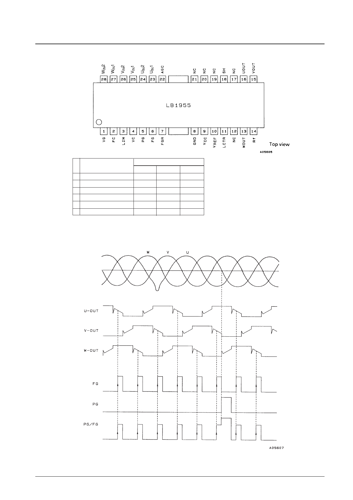
Pin Assignment
LB1955
Truth table
Source → sink
1
W phase → V phase
2
W phase → U phase
3
V phase → U phase
4
V phase → W phase
5
U phase → W phase
6
U phase → V phase
Hall input logic
U
V
W
H
H
L
H
L
L
H
L
H
L
L
H
L
H
H
L
H
L
Note: The Hall input "H" and "L" values are defined as follows: "H" means that for that phase the (+) input is higher than the (-) input, and "L" means that for
that phase the (+) input is lower than the (-) input. However, note that an input potential difference corresponding to the Hall to output gain is required.
Timing Charts
Hall inputs
Synthesized
waveform
Note: The Hall inputs are defined as follows: U = UIN1 – UIN2, V = VIN1 – VIN2, and W = WIN1 – WIN2.
Inputs to the Hall input pins must be applied in the phase order shown in the timing chart.
No. 5452-3/7
Share Link: 