LAN9115 Просмотр технического описания (PDF) - SMSC -> Microchip
Номер в каталоге
Компоненты Описание
Список матч
LAN9115 Datasheet PDF : 131 Pages
| |||
Highly Efficient Single-Chip 10/100 Non-PCI Ethernet Controller
Datasheet
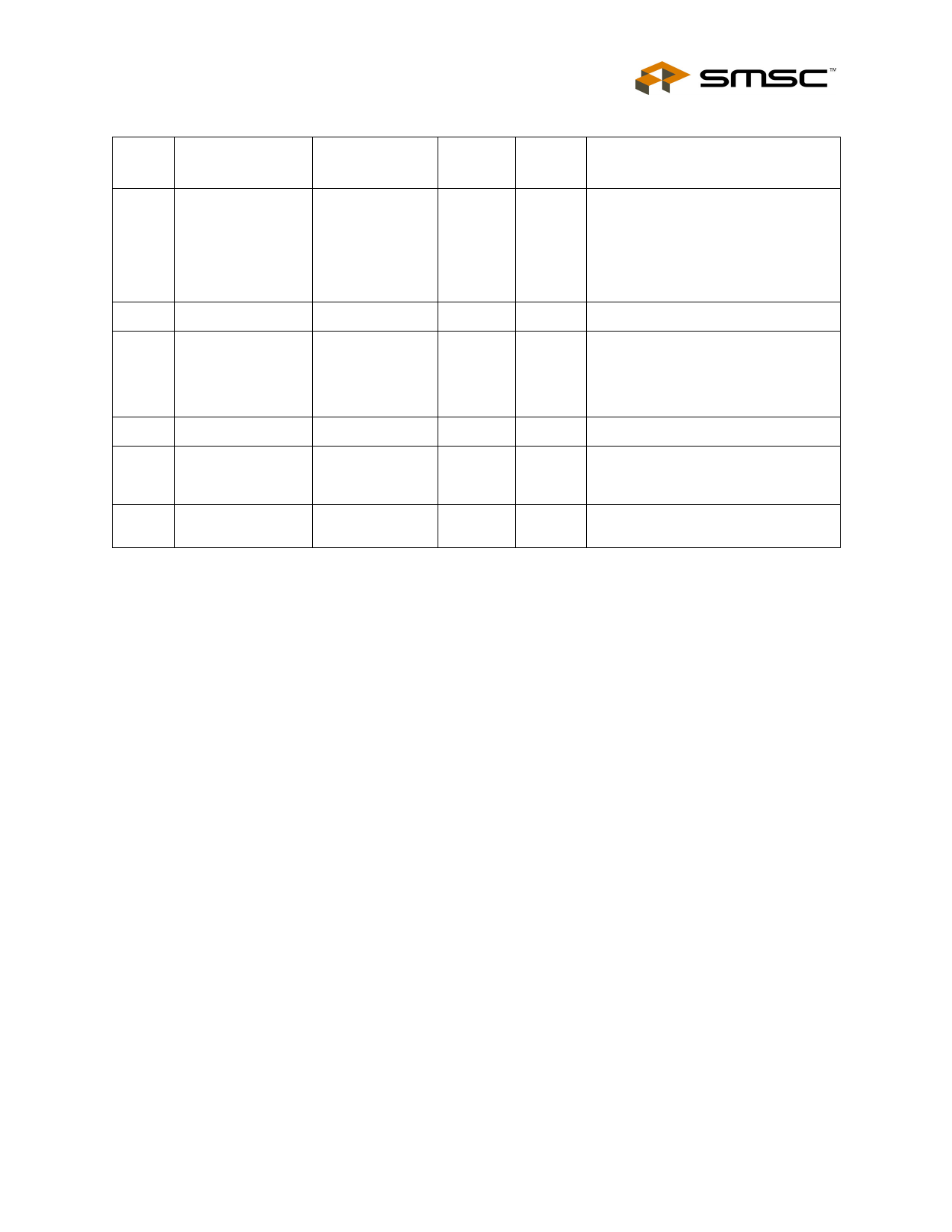
Table 2.5 System and Power Signals (continued)
PIN
NO.
3,65
1,66
7
4
8
11
NAME
SYMBOL
BUFFER NUM
TYPE
PINS
DESCRIPTION
Core Voltage
VDD_CORE
P
Decoupling
Core Ground
GND_CORE
P
PLL Power
VDD_PLL
P
PLL Ground
VSS_PLL
P
Reference Power
VDD_REF
P
Reference Ground
VSS_REF
P
2
1.8 V from internal core regulator.
Both pins must be connected
together externally and then tied to a
10uF 0.1-Ohm ESR capacitor, in
parallel with a 0.01uF capacitor to
Ground next to each pin. See
Note 2.1
2
Ground for internal digital logic
1
1.8V Power from the internal PLL
regulator. This external pin must be
connected to a 10uF 0.1-Ohm ESR
capacitor, in parallel with a 0.01uF
capacitor to Ground. See Note 2.1
1
GND for the PLL
1
Connected to 3.3v power and used
as the reference voltage for the
internal PLL
1
Ground for internal PLL reference
voltage
Note 2.1
Please refer to the SMSC application note AN 12.5 titled “Designing with the LAN9118 -
Getting Started”. It is also important to note that this application note applies to the whole
SMSC LAN9118 family of Ethernet controllers. However, subtle differences may apply.
SMSC LAN9115
19
DATASHEET
Revision 1.1 (05-17-05)
Share Link: 