LA8638NV Просмотр технического описания (PDF) - SANYO -> Panasonic
Номер в каталоге
Компоненты Описание
Список матч
LA8638NV Datasheet PDF : 16 Pages
| |||
LA8638NV
Usage Notes
1. Internal Reference Voltages
The chip uses the following reference voltages internally.
Pin 29 (VREF) Power supply voltage follower (approximately 0.5 VCC)
Pin 4 (VREF2) Fixed voltage (approximately 1.25 V)
2. Microphone Amplifier
Do not use the microphone amplifier as a buffer amplifier (non-reversing, zero-gain amplifier) because it is designed
for high-gain operation—that is, gains above 6 dB—and is susceptible to oscillation below that level.
For proper circuit balance, use the same resistance value for the bias resistor (between pins 28 and 29) and the
feedback resistor (between pins 26 and 27).
3. BTL Amplifier
The built-in BTL amplifier is designed for ceramic speakers only. Do not use it to drive a dynamic speaker.
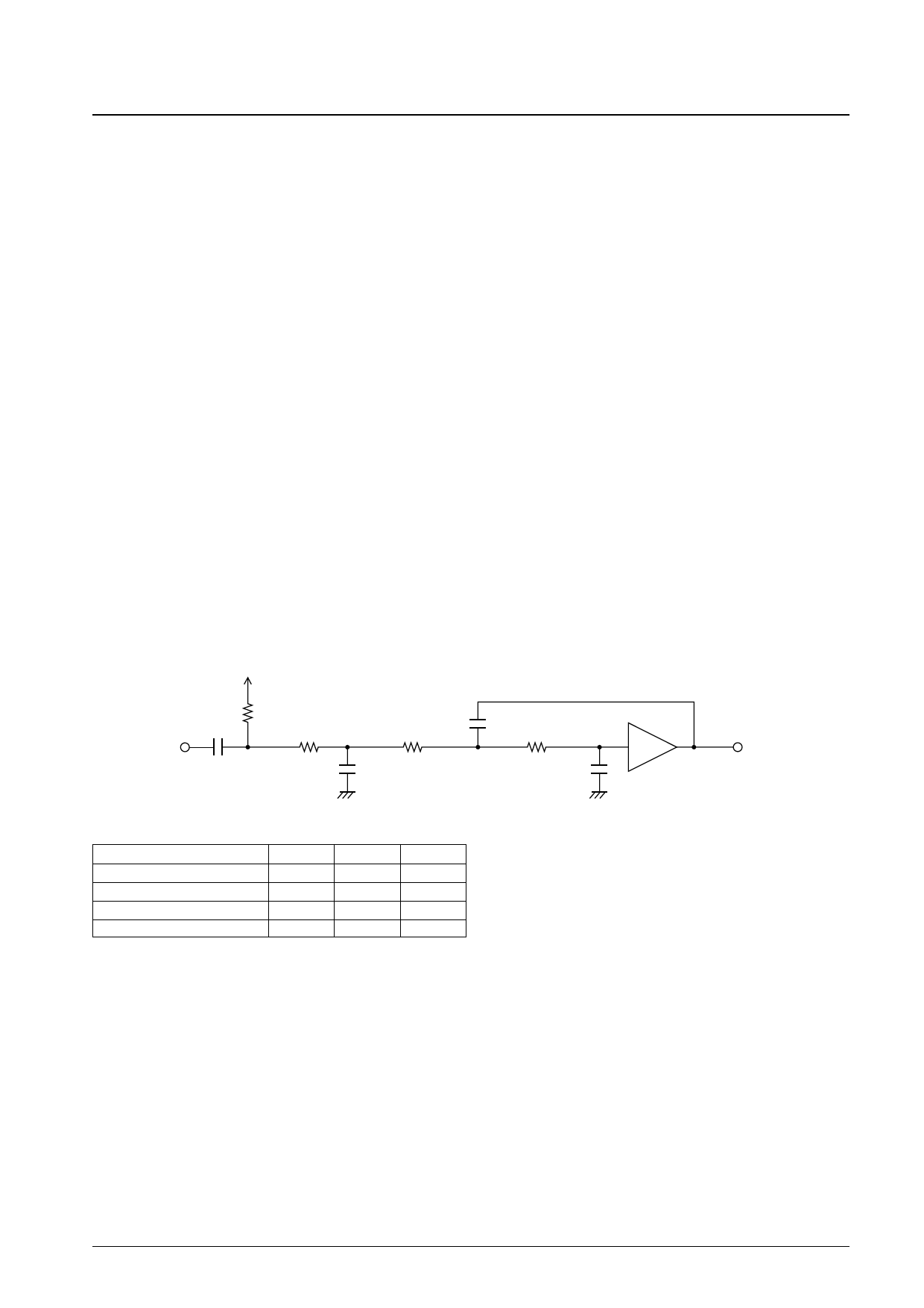
4. Receiver Input Filter
The receiver input filter uses external capacitors and resistors to determine the cutoff frequencies. The external circuit
constants may be easily derived from the standardized circuit constants. Start by making all resistors the same size
and determine the capacitances required to achieve the desired cutoff frequencies from the circuit constants in Table
1. Then, because capacitors are not available for such precise values, choose the closest ones available and then fine-
tune the resistances. (As a result, the final resistances will not necessarily be equal.)
Once the filter constants have been established, choose the bias voltage supply resistor RB so that the total DC
resistance between pins 4 and 5 is on the order of 120 kΩ to standardize the voltage drop across this path due to the
small base current from the transistor in the pin 5 input circuit and thus the duty factor for the data shaper at the next
stage.
Vref
RB
CIN
Ca=Xa/2πfcR
R
R
C3
C2
R
+
C1
Table 1. Standardized Circuit Constants
Lowpass filter type
X1
X2
X3
Second-order Butterworth function 0.7071
1.4142
—
Third-order Butterworth function 0.2025
3.5468
1.3926
Second-order Bessel function
0.5000
0.6667
—
Third-order Bessel function
0.1451
0.8136
0.5647
The Bessel functions for cutoff frequencies do not incorporate the notion of 3-
dB attenuation. The 3-dB attenuation frequency for the second-order function
is 1.38 fc; for the third-order function, 1.75 fc.
A13522
5. Splatter Filter Cutoff Frequency
The resistance between pin 24 and ground determines the cutoff frequency for the splatter filter in the transmitter
circuit. (See Graph 1 on p. 8.) To fine-tune this frequency, use two resistors and adjust them to achieve the desired
frequency.
6. Gain Change Levels
The resistance between pins 29 and 30 determines the gain change level for the transmitter circuits. (See Graph 2 on
p. 8.)
The resistance between pin 9 and ground determines the gain change level for the receiver circuits. (See Graph 3 on
p. 8.)
No. 6627-6/16
Share Link: 