ISL8204M Просмотр технического описания (PDF) - Intersil
Номер в каталоге
Компоненты Описание
Список матч
ISL8204M Datasheet PDF : 20 Pages
| |||
ISL8204M, ISL8206M
add a small delay compared to the soft-start times. The
COMP/EN will continue to ramp to ~1V.
From T1, there is a nominal 6.8ms delay, which allows
the PVCC pin to exceed 6.5V (if rising up towards 12V),
so that the internal bias regulator can turn on cleanly. At
the same time, the ISET pin is initialized by disabling the
low-side gate driver and drawing ISET (nominal 21.5µA)
through RSETI. This sets up a voltage that will represent
the ISET trip point. At T2, there is a variable time period
for the OCP sample and hold operation (0.0ms to 3.4ms
nominal; the longer time occurs with the higher
overcurrent setting). The sample and hold operation uses
a digital counter and DAC to save the voltage, so the
stored value does not degrade, as long as the PVCC is
above VPORR (see “Overcurrent Protection (OCP)” on
page 12 for more details on the equations and variables).
Upon the completion of sample and hold at T3, the soft-
start operation is initiated, and the output voltage ramps
up between T4 and T5.
CCOOMMPP//EENN
TT0 TT1
IISSEETT
VVOOUUTT
FIGURE 18. ISET AND SOFT-START OPERATION
Soft-Start and Pre-Biased Outputs
The soft-start internally ramps the reference on the
non-inverting terminal of the error amp from 0V to 0.6V
in a nominal 6.8ms. The output voltage will follow the
ramp from zero to it’s final value in the same 6.8ms (the
actual ramp seen on VOUT will be less than the nominal
time), due to some initialization timing between T3 and
T4.
The ramp is created digitally, so there will be 64 small
discrete steps. There is no simple way to change this
ramp rate externally.
After an initialization period (T3 to T4), the error amplifier
(COMP/EN pin) is enabled and begins to regulate the
converter's output voltage during soft-start. The
oscillator's triangular waveform is compared to the
ramping error amplifier voltage. This generates PHASE
pulses of increasing width that charge the output
capacitors. When the internally generated soft-start
voltage exceeds the reference voltage (0.6V), the
soft-start is complete and the output should be in
regulation at the expected voltage. This method provides
a rapid and controlled output voltage rise; there is no
large inrush current charging the output capacitors. The
entire start-up sequence from POR typically takes up to
17ms; up to 10.2ms for the delay and OCP sample and
6.8ms for the soft-start ramp.
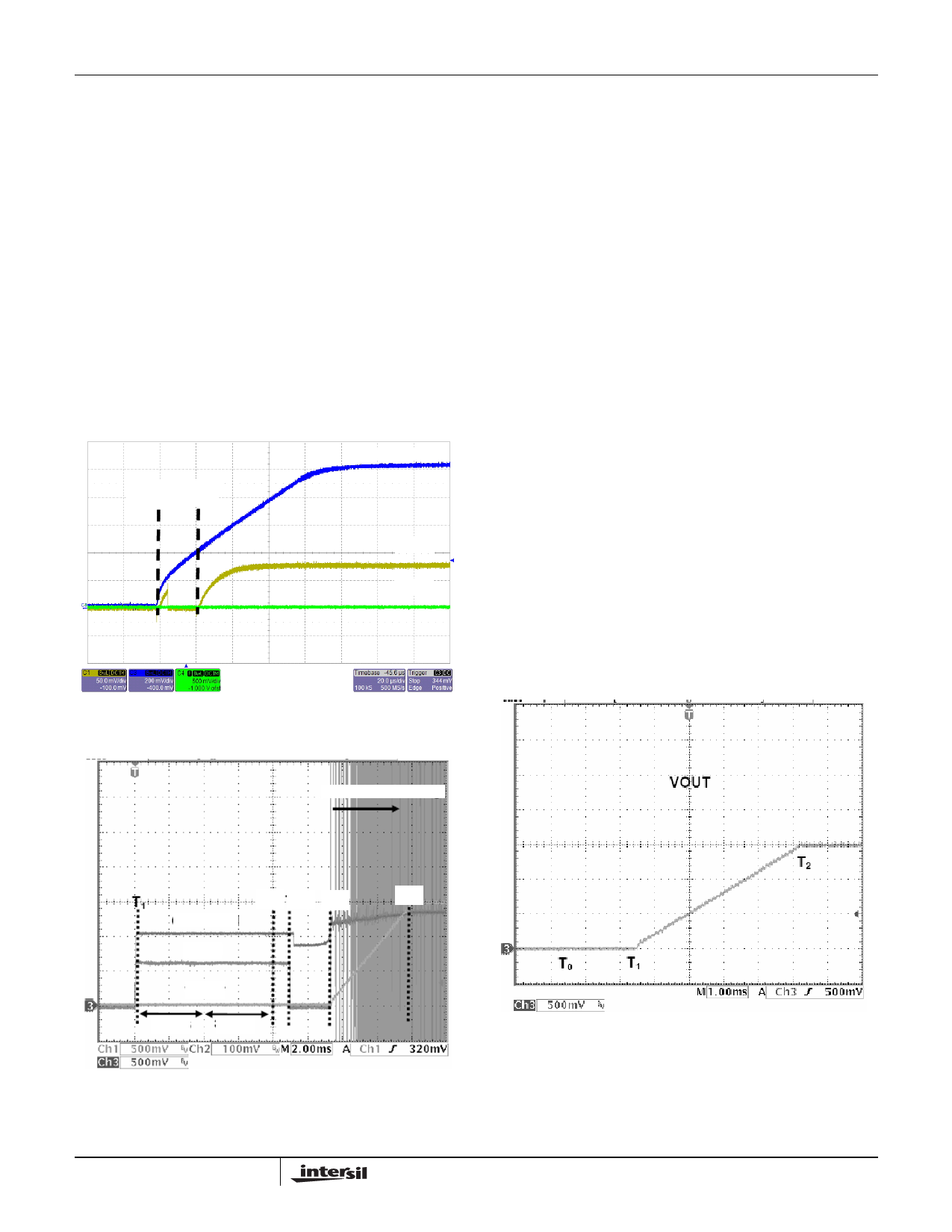
Figure 20 shows the normal curve for start-up;
initialization begins at T0, and the output ramps between
T1 and T2. If the output is pre-biased to a voltage less
than the expected value (as shown Figure 21), neither
internal MOSFET will turn on until the soft-start ramp
voltage exceeds the output; VOUT starts seamlessly
ramping from there.
START SWITCHING
T2 T3 T4
T5
COMP/EN
ISET
VOUT
3.4ms 3.4ms
FIGURE 19. ISET AND SOFT-START OPERATION
11
FIGURE 20. NORMAL START-UP
FN6999.1
February 25, 2010
Share Link: 