IDT82V2052E Просмотр технического описания (PDF) - Integrated Device Technology
Номер в каталоге
Компоненты Описание
Список матч
IDT82V2052E Datasheet PDF : 70 Pages
| |||
IDT82V2052E
2 PIN DESCRIPTION
DUAL CHANNEL E1 SHORT HAUL LINE INTERFACE UNIT
Table-1 Pin Description
Name
TTIP1
TTIP2
TRING1
TRING2
Type
Analog
Output
RTIP1
RTIP2
Analog
Input
Pin No.
63
78
62
79
67
74
Description
TTIPn1/TRINGn: Transmit Bipolar Tip/Ring for Channel 1~2
These pins are the differential line driver outputs and can be set to high impedance state globally or individually. A logic high
on THZ pin turns all these pins into high impedance state. When THZ bit (TCF1, 03H...)2 is set to ‘1’, the TTIPn/TRINGn in
the corresponding channel is set to high impedance state.
In summary, these pins will become high impedance in the following conditions:
• THZ pin is high: all TTIPn/TRINGn enter high impedance;
• THZn bit is set to 1: the corresponding TTIPn/TRINGn become high impedance;
• Loss of MCLK: all TTIPn/TRINGn pins become high impedance;·
• Loss of TCLKn: the corresponding TTIPn/TRINGn become HZ (exceptions: Remote Loopback; Transmit internal pat-
tern by MCLK);
• Transmitter path power down: the corresponding TTIPn/TRINGn become high impedance;
• After software reset; pin reset and power on: all TTIPn/TRINGn enter high impedance.
RTIPn/RRINGn: Receive Bipolar Tip/Ring for Channel 1~2
These signals are the differential receiver inputs.
RRING1
RRING2
TD1/TDP1
I
TD2/TDP2
TDN1
TDN2
66
75
37 TDn: Transmit Data for Channel 1~2
23 When the device is in single rail mode, the NRZ data to be transmitted is input on this pin. Data on TDn pin is sampled into
the device on the active edge of TCLKn and is encoded by AMI or HDB3 line code rules before being transmitted. In this mode,
36 TDNn should be connected to ground.
24
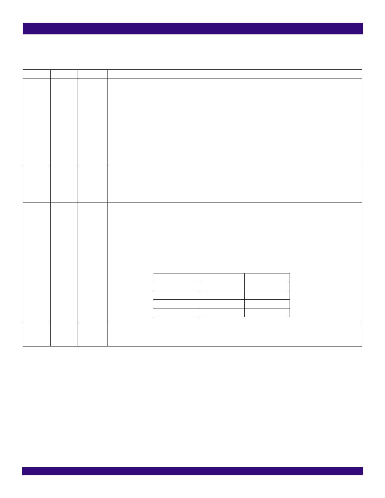
TDPn/TDNn: Positive/Negative Transmit Data
When the device is in dual rail mode, the NRZ data to be transmitted for positive/negative pulse is input on these pins. Data
on TDPn/TDNn pin is sampled into the device on the active edge of TCLKn. The active polarity is also selectable. Refer to
3.2.1 TRANSMIT PATH SYSTEM INTERFACE for details. The line code in dual rail mode is as follows:
TDPn
0
0
1
1
TDNn
0
1
0
1
Output Pulse
Space
Positive Pulse
Negative Pulse
Space
TCLK1
I
TCLK2
38 TCLKn: Transmit Clock for Channel 1~2
22 This pin inputs a 2.048 MHz transmit clock. The transmit data at TDn/TDPn or TDNn is sampled into the device on the active
edge of TCLKn. If TCLKn is missing3 and the TCLKn missing interrupt is not masked, an interrupt will be generated.
Notes:
1. The footprint ‘n’ (n = 1~2) represents one of the two channels.
2. The name and address of the registers that contain the preceding bit. Only the address of channel 1 register is listed, the rest addresses are represented by ‘...’. Users can find
these omitted addresses in the Register Description section.
3. TCLKn missing: the state of TCLKn continues to be high level or low level over 70 MCLK cycles.
PIN DESCRIPTION
9
December 12, 2005
Share Link: 