RF2917 Просмотр технического описания (PDF) - RF Micro Devices
Номер в каталоге
Компоненты Описание
Список матч
RF2917 Datasheet PDF : 14 Pages
| |||
RF2917
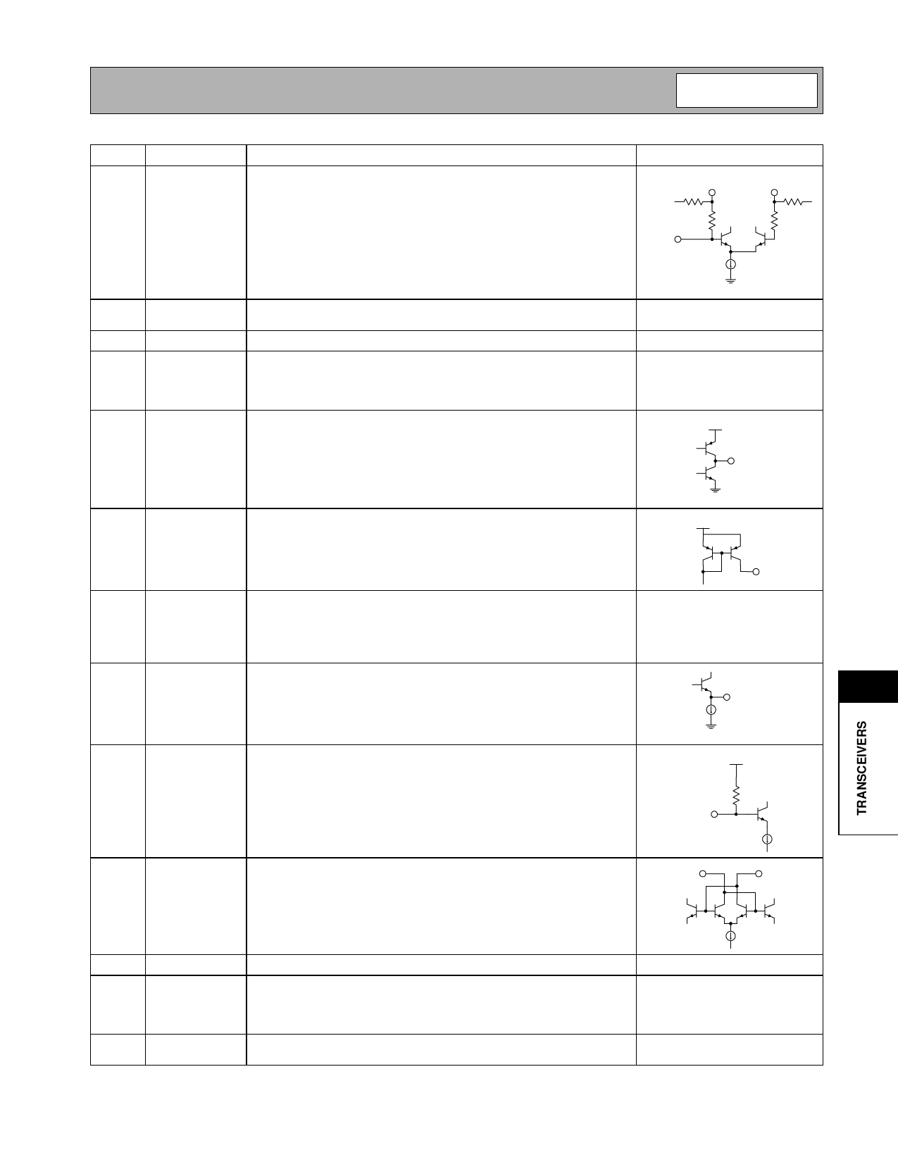
Pin Function Description
Interface Schematic
16
IF2 IN
Inverting input to the 60dB limiting amplifier strip. A 10 nF DC blocking
capacitor is required on this input. The IF2 IN input presents a nominal
330Ω input resistance and interfaces directly to 10.7MHz ceramic fil-
ters.
IF2 BP+
60 kΩ
330
IF2 BP-
60 kΩ
330
IF2 IN
17
IF2 BP+ DC feedback node for the 60dB limiting amplifier strip. A 100nF bypass See pin 16.
capacitor from this pin to ground is required.
18
IF2 BP- See pin 17.
See pin 16.
19
VCC3
This pin is used to supply DC bias to the 60dB IF limiting amplifier. An
IF bypass capacitor should be connected directly to this pin and
returned to ground. A 10 nF capacitor is recommended for 10.7MHz IF
applications.
20
MUTE
This pin is used to select FM, FSK, or mute at the FM OUT pin.
MUTE>Vcc - 0.4V turns the FM OUT signal off. MUTE<0.4V turns the
FM OUT signal on for FSK digital data. When MUTE is left floating, the
FM OUT signal is linear FM.
VCC
MUTE
21
RSSI
A DC voltage proportional to the received signal strength is output from
this pin. The output voltage increases with increasing signal strength.
22
FM OUT Demodulated output from the discriminator/demodulator. Output levels
on this are CMOS compatible in FSK mode (see pin 20). In linear FM
mode, the demodulated signal level is approximately 240mVpp on a
DC voltage offset. The magnitude of the load impedance is intended to
be 1MΩ or greater.
23
IF2 OUT IF output from the 60dB limiting amplifier strip. This pin is intended to
be connected to pin 24 through a 5pF capacitor (for 10.7MHz IF appli-
cations). This capacitor in conjunction with a tank resonant at the IF fre-
quency connected from pin 24 to ground is used to form an FM
discriminator.
24 DEMOD IN This pin is the input to the FM demodulator. This pin is NOT AC cou-
pled. Therefore, a DC blocking capacitor is required on this pin to avoid
a DC path to ground. A DC blocked LC tank resonant at the IF or
ceramic discriminator should be connected to this pin.
VCC
RSSI
IF2 OUT
VCC
DEMOD IN
10 kΩ
25
RESNTR- This port is used to supply DC voltage to the VCO as well as to tune the
RESNTR+
center frequency of the VCO. Equal value inductors should be con-
nected to this pin and pin 26.
RESNTR-
11
26 RESNTR+ See pin 25.
See pin 25.
27
VCC2
This pin is used to supply DC bias to the VCO, prescaler, and PLL. An
IF bypass capacitor should be connected directly to this pin and
returned to ground. A 10nF capacitor is recommended for 10.7MHz IF
applications.
28
GND4
GND4 is the ground shared on chip by the VCO, prescaler, and PLL
electronics.
Rev B2 010118
11-133
Share Link: 